
Manual

Model 5204 User Guide Issue 2, August 2015
Studio Technologies, Inc. Page 11
Model 5204
Dual Line Input to Dante Interface
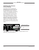
How to Identify a Specific
Model 5204
The Dante Controller software application
offers an identify command that can be
used to help locate a specific Model 5204.
When identify is selected for a specific unit
its meter LEDs will light in a unique pat-
tern. In addition, the SYS and SYNC LEDs,
located directly below the etherCON con-
nector on the back panel, will slowly flash
green. After a few seconds the LED iden
-
tification patterns will cease and normal
Model 5204 level meter and Dante status
LED operation will again take place.
Level Meters
Two 7-step LED meters will display the
level of the two Dante transmitter (output)
channels. The meter steps are calibrated
in dBFS which indicates the number of
dB below the maximum possible digital
signal level. The maximum level, 0 dBFS,
is the digital audio reference level equal to
“full scale.” Full scale refers to the maxi-
mum level possible for a sine wave before
“digital clipping.” In typical applications
a signal level of –20 dBFS would be the
desired nominal (normal average) value.
The five meter steps that have a threshold
of –20 dBFS and less light with the color
green. The step that lights at –15 dBFS
and greater is yellow in color and indicates
a “hot” or above average signal level. The
top step lights red in color when a signal
levels is –5 dBFS or greater, indicating
that a potentially “clipped” (distorted due
to excessive level) signal is present.
Input A
The signal connected to the tip (left chan-
nel) connection of line input A’s 3.5 mm
jack is associated with Dante transmitter
(output) channel 1. The ring (right channel)
connection of the 3.5 mm jack is associ
-
ated with Dante transmitter channel 2. The
push-in/push-out rotary control adjusts the
input level of both channels of line input
A. In its fully counterclockwise position the
input signal are essentially off (muted). Ad-
just the control such that normal input sig-
nals will cause the five green LEDs to light.
Peak signals can cause the yellow LED
to light on occasion. But the yellow LED
should never be continuously lit. The red
LED should never light, except possibly in
the case of an extreme peak. The red LED
lighting on a regular basis indicates that
the signal level is at risk of reaching digital
0 (0 dBFS) which is destructive to audio
quality.
Input B
The signal connected to line input B’s
channel 1 3-pin female XLR connec-
tor is associated with Dante transmitter
(output) channel 1. The signal connected
to line input B’s channel 2 XLR connec-
tor is associated with Dante transmitter
(output) channel 2. The push-in/push-out
rotary control adjusts the input level of both
channels of line input B. In its fully coun-
terclockwise position the input signals are
essentially off (muted). Adjust the control
such that normal input signals will cause
the five green LEDs to light. Peak signals
can cause the yellow LED to light on occa-
sion. But the yellow LED should never be
continuously lit. The red LED should never
light, except possibly in the case of an
extreme peak. The red LED lighting on a
regular basis indicates that the signal level
is at risk of reaching digital 0 (0 dBFS)
which is destructive to audio quality.