
Manual

Issue 2, August 2015 Model 5204 User Guide
Page 10 Studio Technologies, Inc.
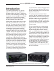
Model 5204
Dual Line Input to Dante Interface
The Model 5204 has a default Dante de-
vice name of ST-M5204 and a unique suf-
fix. The suffix identifies the specific Model
5204 that is being configured (it relates to
the MAC address of the Ultimo integrated
circuit). The two Dante transmitter chan-
nels have default names of Ch1 and Ch2.
Using Dante Controller the default device
and channel names can be revised as
appropriate for the specific application.
Operation
At this point an Ethernet connection with
Power-over-Ethernet (PoE) capability
should have been made. The unit’s Dante
configuration settings should have been
selected using Dante Controller software
application. At a minimum the Model
5204’s two Dante transmitter channels
should have been routed to receiver
channels on an associated device. Analog
signal source connections to line input A
and line input B should have been made
as desired. A device may have been con
-
nected to the USB dedicated charging
port. Normal operation of the Model 5204
can now begin.
Initial Operation
The Model 5204 will immediately begin to
function as soon as a Power-over-Ethernet
(PoE) power source is connected. At this
time the USB dedicated charging port will
become functional. However, full operation
may take up to 20 seconds to begin. Upon
initial power up the four status LEDs locat-
ed on the back panel will begin to light. The
meter LEDs on the front panel will light in a
test sequence. After the meter LEDs com-
plete their test sequence one meter LED
associated with channel 1 and one meter
LED associated with channel 2 will briefly
light to indicate the version number of the
unit’s firmware (embedded software). (Un-
derstanding how to “read” the application
firmware number will be discussed in detail
later in this guide.) Once that sequence
has completed and the Dante connection
has been established full operation will
begin.
Ethernet, PoE, and Dante
Status LEDs
Four status LEDs are located below the
Ethernet connector on the Model 5204’s
back panel. The PoE LED will light green
to indicate that Power-over-Ethernet (PoE)
associated with the connected Ethernet
signal is providing operating power for the
Model 5204. The LINK/ACT LED will light
green whenever an active connection to
a 100 Mb/s Ethernet network has been
established. It will flash in response to data
packet activity. The SYS and SYNC LEDs
display the operating status of the Dante
interface and associated network. The
SYS LED will light red upon Model 5204
power up to indicate that the Dante inter-
face is not ready. After a short interval it
will light green to indicate that it is ready to
pass data with another Dante device. The
SYNC LED will light red when the Model
5204 is not synchronized with a Dante
network. It will light solid green when the
Model 5204 is synchronized with a Dante
network and an external clock source
(timing reference) is being received. It will
slowly flash green when the Model 5204 is
part of a Dante network and is serving as
a clock master.