
Manual

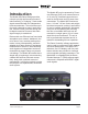
Table Of Contents
- Model 48D Dante Bridge
- Table of Contents
- Revision History
- Introduction
- Getting Started
- Configuration
- Operation
- Technical Notes
- Specifications
- Appendix A–Model 48D Front-Panel LCD Display Menu Structure
- Appendix B–Graphical Description of Model 48D Rack-Mount Installation Kit for One Model 48D Unit (Order Code: RMBK-11)
- Appendix C–Graphical Description of Model 48D Rack-Mount Installation Kit for Two Model 48D Units (Order Code: RMBK-12)

Model 48D User Guide Issue 2, July 2018
Studio Technologies, Inc. Page 9
Locating the Model 48D
The location of the Model 48D will primar-
ily depend on being within the 100-meter
(325-foot) twisted pair Ethernet cable limita-
tion. Each of the two Ethernet ports on the
Model 48D would have to be within that
length limit. But that requirement can be
overcome by using fiber-optic interconnects
between the Model 48D-related Ethernet
switches and the other Ethernet switches
in the local-area-networks (LANs).
Protecting the Enclosure
The Model 48D is shipped as a self-
contained unit suitable for portable use
or placement in a semi-permanent loca-
tion. Installed on the bottom of the chassis
are screw-on “bump on” protectors (also
known as “rubber feet”). These are useful
if the unit is going to be placed on surfaces
where scratching of either the Model 48D
or the surface material could take place.
The “feet” can be removed, without the use
of a tool, when rack- or custom-mounting
the unit.
Rack Mounting
For some applications it might be desirable
to mount one or two Model 48D units into
one space (1U) of a 19-inch rack enclosure.
Rack-mount installation kits, purchased
separately, are available from Studio Tech-
nologies. The following sections provide
details on how to use the rack-mount kits.
Refer to Appendices B and C of this guide
for graphical descriptions of how to attach
the rack-mount kits.
Rack-Mounting One Model 48D
Rack-mount installation kit RMBK-11 is
used to allow rack mounting of one Model
48D unit. The kit contains one standard
rack bracket, one long rack bracket, and
four 6-32 thread-pitch Phillips-head ma-
chine screws. Refer to Appendix B for a
visual explanation.
Begin the installation by removing the
four “bump on” protectors from the bot-
tom of the Model 48D’s chassis. They can
be removed using one’s fingers to rotate
them counterclockwise; no tool is required.
It’s probably a good idea to store the four
“bump on” protectors for possible later use.
With assistance from a #2 Phillips-tip
screw driver, use the machine screws to
attach the standard and long rack brackets
to the sides of the Model 48D’s enclosure.
The screws will mate with the threaded
fasteners that can be seen on the sides of
the Model 48D’s enclosure, near the front
of the unit.
Mount the standard rack bracket to the left
side of the Model 48D (when viewed from
the front) if the unit needs to be located on
the left side of the rack enclosure. Then
mount the long rack bracket to the right
side of the Model 48D. Mount the brack-
ets in the opposite orientation should the
Model 48D need to be located on the right
side of the rack enclosure.
Once the “bump on” protectors have been
removed and the standard and long rack
brackets have been installed the Model
48D will be ready to be mounted into the
designated equipment rack. One space
(1U or 1.75 vertical inches) in a standard
19-inch equipment rack is required. Secure
the unit into the equipment rack using two
mounting screws per side.
Rack-Mounting Two Model 48D Units
Rack-mount installation kit RMBK-12
is used to allow one-space (1U) rack