
Manual

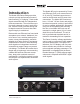
Table Of Contents
- Model 48D Dante Bridge
- Table of Contents
- Revision History
- Introduction
- Getting Started
- Configuration
- Operation
- Technical Notes
- Specifications
- Appendix A–Model 48D Front-Panel LCD Display Menu Structure
- Appendix B–Graphical Description of Model 48D Rack-Mount Installation Kit for One Model 48D Unit (Order Code: RMBK-11)
- Appendix C–Graphical Description of Model 48D Rack-Mount Installation Kit for Two Model 48D Units (Order Code: RMBK-12)

Issue 2, July 2018 Model 48D User Guide
Page 10 Studio Technologies, Inc.
mounting of two Model 48D units. The
kit contains two standard rack brackets,
two joiner plates, eight 6-32 thread-pitch
Phillips-head machine screws, and two
2-56 thread-pitch Torx T7 thread-forming
machine screws. Refer to Appendix C for
a visual explanation.
Begin installing the kit by removing the four
“bump on” protectors from the bottom of
each chassis. They can be removed using
one’s fingers to rotate them counterclock-
wise; no tool is required. Store the eight
“bump on” protectors for possible later use.
With assistance from a #2 Phillips-tip
screw driver, use two of the 6-32 machine
screws to attach one of the standard rack
brackets to the left side (when viewed from
the front) of one of the Model 48D units.
The screws will mate with the threaded
fasteners that can be seen on the sides of
the Model 48D’s enclosure, near the front
of the unit. Using two more of the 6-32
machine screws, attach one of the joiner
plates to the right side of that same Model
48D unit.
Again using two of the 6-32 machine
screws, attach the second standard rack
bracket to the right side of the second
Model 48D unit. Using the final two 6-32
machine screws, attach the second joiner
plate to the left side of the second Model
48D unit with an orientation of 180 degrees
from the way in which the first plate was
installed.
To complete the assembly, “join” the
units together by sliding each joiner plate
through the other. The grooves in each
joiner plate will carefully align with each
other and form a relatively tight bond. Line
up the two units so that the front panels
form a common plane. With the aid of a
Torx T7 driver, use the two 2-56 machine
screws to secure the two joiner plates
together. The screws should fit snugly into
the small openings formed by the mating
of the two joiner plates.
Once the “bump on” protectors are re-
moved and the assembly created, the two
Model 48D units are ready to be mounted
into the designated equipment rack. One
space (1U or 1.75 vertical inches) in a
standard 19-inch equipment rack is re-
quired. Secure the unit into the equipment
rack using two mounting screws per side.
Ethernet Connections
The Model 48D has two network connec-
tions called Network A and Network B.
These are associated with the two net-
works that are going to “bridged” by the
Model 48D. Each network connection
needs to support 100BASE-TX (100 Mb/s
over twisted-pair) for the Model 48D’s
Dante audio-over-Ethernet connectivity.
10BASE-T connections are not sufficient
for Model 48D operation. 1000BASE-T
(“GigE”) connections are not supported
unless they can automatically “fall back”
to 100BASE-TX operation.
An Ethernet connection that supports
Power-over-Ethernet (PoE) is preferred
for connecting to Network A as it will pro-
vide both data and operating power for the
Model 48D. To support power manage-
ment functionality on an associated PoE
switch (PSE) the Model 48D’s Network A
connection will enumerate itself as a PoE
class 1 (very low power) device. If PoE is
not available on Network A an external
12 volt DC power source can be con-
nected. This will be discussed in a later
subsection of the guide.