Model 48D Dante® Bridge User Guide Issue 2, July 2018 This User Guide is applicable for serial numbers M48D-00151 and later with application firmware 1.1 and later and Dante firmware 1.0.0 (UltimoX4 4.1.2.1) Copyright © 2018 by Studio Technologies, Inc., all rights reserved www.studio-tech.
This page intentionally left blank.
Table of Contents Revision History ................................................................... 4 Introduction ........................................................................... 5 Getting Started ..................................................................... 8 Configuration ........................................................................ 11 Operation .............................................................................. 15 Technical Notes ...............................
Revision History Issue 2, July 2018: 1. Added additonal content. Issue 1, July 2018: 1. Initial release. Issue 2, July 2018 Page 4 Model 48D User Guide Studio Technologies, Inc.
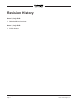
Introduction The Model 48D Dante® Bridge provides a simple yet high-performance means of interconnecting, or “bridging,” Dante audio signals associated with two independent local-area-networks. The unit allows up to four audio channels to pass in each direction. Internal circuitry provides timing and bit-depth correction to ensure that audio signal integrity is maintained.
Dante Audio-over-Ethernet Audio data is sent to and received from the Model 48D using the Dante audio-overEthernet media networking technology. Two separate network interfaces allow completely independent configurations. Audio signals with a sample rate of 44.1, 48, 88.2, and 96 kHz and a bit depth of up to 24 are supported. Up to four audio channels in each direction can pass (be “bridged”) between the Model 48D’s two network interfaces.
support a sample rate of 96 kHz, while the other devices connected to the network only support 48 kHz. In this situation the Model 48D would allow two channels in each direction to interconnect, while still maintaining the required 96 kHz and 48 kHz sample rates. In this application it’s interesting to note that both of the Model 48D’s Ethernet ports would be connected to the same local-area-network (LAN).
RJ45 plugs, etherCON allows a ruggedized and locking interconnection for harsh or high-reliability environments. The Model 48D’s operating power can be provided by a Power-over-Ethernet (PoE)-compliant Ethernet signal that’s connected to the Model 48D’s Network A interface. For network management purposes the interface will report to the power sourcing equipment (PSE) that it is a class 1 (very low power) device. If PoE is not available the unit can also be powered using an external source of 12 volts DC.
Locating the Model 48D The location of the Model 48D will primarily depend on being within the 100-meter (325-foot) twisted pair Ethernet cable limitation. Each of the two Ethernet ports on the Model 48D would have to be within that length limit. But that requirement can be overcome by using fiber-optic interconnects between the Model 48D-related Ethernet switches and the other Ethernet switches in the local-area-networks (LANs).
mounting of two Model 48D units. The kit contains two standard rack brackets, two joiner plates, eight 6-32 thread-pitch Phillips-head machine screws, and two 2-56 thread-pitch Torx T7 thread-forming machine screws. Refer to Appendix C for a visual explanation. Begin installing the kit by removing the four “bump on” protectors from the bottom of each chassis. They can be removed using one’s fingers to rotate them counterclockwise; no tool is required.
No problems will occur if an Ethernet signal that supports Power-over-Ethernet (PoE) is connected to the RJ45 receptacle associated with the Model 48D’s Network B. It will not enumerate (announce) itself to the PoE-enabled switch as a PoE device nor will it supply power to the Model 48D. Only if a PoE-supporting Ethernet signal is connected to Network A will operating power be supplied.
As previously discussed, the Model 48D’s LCD display and pushbutton switches allow changes to both of the unit’s Dante network interfaces. But it’s important to note that when using Dante Controller to make changes to the operation of a specific network interface one must run a designated instance of the application.
of input channels). Note that the Ultimo integrated circuit limits the number of Dante flows to four, two in each direction. These can either be unicast, multicast, or a combination of the two. The Model 48D uses two Ultimo integrated circuits and, as expected, each is limited to two flows for transmitter channels and two flows for receiver channels. Each Model 48D has four Dante output (transmitter) channels and four Dante input (receiver) channels.
name of ST-M48D-B-, again followed by a unique suffix that’s based on the MAC address of the Ultimo integrated circuit. The four Dante input (receiver) channels have the default names of Ch1 In, Ch2 In, Ch3 In, and Ch4 In. The four Dante output (transmitter) channels have the default names of Ch1 Out, Ch2 Out, Ch3 Out, and Ch4 Out. Use Dante Controller to revise the names as would be appropriate for the specific application.
on to the Subnet Mask screen which will display the currently-stored value. Again use the pushbuttons to make any desired changes followed by pressing the Enter button. A prompt will then display asking if a reboot is desired. Select Yes to reboot the interface using the revised IP address and subnet mask values. should have been selected using Dante Controller.
The manner in which the back-panel LINK/ ACT, SYS, and SYNC LEDs light will depend on the characteristics of the connected Ethernet signals and the configuration of the unit’s Dante interfaces. On the front panel the user is presented with four status LEDs, a two-line (18 characters-per-line) back-lit LCD display, and five pushbutton switches. These resources are simple to understand and should prove to be useful during operation and troubleshooting.
indicates that no valid network connection is present on its respective network interface. An LED that is lit green indicates that the associated network has a successful Dante connection and another device is serving as the master clock source. If the network LED is flashing green then it will indicate that both a valid Dante connection is established and that this specific interface is serving as the Dante network’s master clock source.
if the Automatic IP configuration method has been selected. Dante Controller can be used to change a fixed (“static”) IP address. A button-press sequence can also be used to change this value if the Manual IP configuration method has been selected. Refer to the Configuration section of this guide for details. Net A Subnet Mask This field displays the subnet mask value actively being used by the Ethernet interface associated with Network A.
Technical Notes IP Address Assignment By default each of the Model 48D’s Ethernet interfaces will attempt to automatically obtain an IP address and associated settings using DHCP (Dynamic Host Configuration Protocol). If a DHCP server is not detected on an interface then an IP address will automatically be assigned using the link-local protocol. This protocol is known in the Microsoft® world as Automatic Private IP Addressing (APIPA). It is also sometimes referred to as auto-IP.
front-panel pushbutton switches and LCD display allows this information to be determined. The Operation section of this guide provides details on how to use the pushbutton switches. Knowing the Model 48D’s firmware version can be useful when working with factory personnel on application support or troubleshooting situations.
6. At this time the Model 48D is functioning with the newly-saved main firmware and the USB flash drive can be removed. But to be conservative, remove the power source first and then remove the USB flash drive. 7. Apply power to the Model 48D and observe the main firmware version number by viewing the front-panel LCD display upon power up. Ensure that this is the desired version is present. Note that upon power being applied to the Model 48D if the USB flash drive doesn’t have the correct file (M48D.
Specifications Connectors: Power-over-Ethernet (PoE): class 1 (low power, ≤3.84 watts) per IEEE® 802.3af External DC: 4-pin male XLR Power Sources: External: 10 to 18 volts DC, 0.
Appendix A–Model 48D Front-Panel LCD Display Menu Structure Model 48D User Guide Studio Technologies, Inc.
Appendix B–Graphical Description of Model 48D Rack-Mount Installation Kit for One Model 48D Unit (Order Code: RMBK-11) Issue 2, July 2018 Page 24 Model 48D User Guide Studio Technologies, Inc.
Appendix C–Graphical Description of Model 48D Rack-Mount Installation Kit for Two Model 48D Units (Order Code: RMBK-12) Model 48D User Guide Studio Technologies, Inc.