User Guide Issue 1, September 2014 This User Guide is applicable for serial numbers: M46A-01151 and later Copyright © 2014 by Studio Technologies, Inc., all rights reserved www.studio-tech.
This page intentionally left blank.
Table of Contents Introduction ................................................................... 5 Installation ..................................................................... 10 Configuration ................................................................ 16 Advanced Configuration ............................................... 17 Operation ...................................................................... 20 Advanced Operation .....................................................
This page intentionally left blank. Issue 1, September 2014 Page 4 Model 46A User Guide Studio Technologies, Inc.
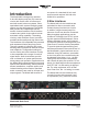
Introduction The Model 46A is designed to interface 2-wire full-duplex party-line (PL) intercom circuits with 4-wire audio circuits associated with matrix intercom systems. Other specialized audio system interfacing applications can also be supported. The Model 46A provides two independent full-featured 2-channel interfaces. Each interface contains two hybrid circuits which include automatic nulling capability.
Powered circuits have a DC voltage present, typically provided by power supplies such as the RTS PS31 or Clear-Com PS232. This DC power, normally 30-32 volts, provides energy for connected devices such as user stations or beltpacks. In this type of application the Model 46A is configured to operate in its external 2-wire power source mode. In this mode the Model 46A’s circuitry maintains the required high-impedance load and, as in all cases, draws no power from the party-line circuit.
microprocessor control to achieve significant trans-hybrid loss. This return-loss “null” is achieved by making a series of adjustments to account for the resistive, inductive, and capacitive conditions that are present on the connected 2-wire partyline circuit. The party-line’s conditions are the sum of the impact made by the type and quantity of cable, the connected userdevices, and the intercom power source.
offering a clear view of the 2-wire DC power and auto null functions. Pro Audio Quality The Model 46A’s audio circuitry was designed in the spirit of professional audio equipment, rather than that found in typical party-line intercom gear. Highperformance components are used throughout, providing low-distortion, lownoise, and high headroom. Using passive and active filters, the frequency response is limited to approximately 100 Hz to 8 kHz.
Simple Installation The Model 46A uses standard 3-pin XLR connectors to allow convenient interconnection in most broadcast and general audio environments. For flexibility, access to the 2-wire party-line intercom interfaces can be made using the connectors provided on both the front and back panels. In permanent installations the back-panel connectors will typically be utilized.
typically connected to 2-wire party-line circuits. By adding DC power sources to the Model 46A’s 2-wire interfaces, the need for external intercom power supplies could often be eliminated. The final step was to create a physical package that would provide significant resources in a form that allowed simple and reliable integration with other equipment. This was accomplished by including two 2-channel interfaces in a one-rack-space enclosure.
4-Wire Line Inputs As previously mentioned, each of the Model 46A’s two interfaces allows two analog line-level audio sources to be connected. The source for these signals will typically be ports on a matrix intercom system. It’s also possible that the signals will come from other devices, such as a fiber optic or copper-based audio transmission system. The 4-wire input circuitry is balanced, capacitor coupled, transformer isolated, and has an impedance of 13 k ohms.
Model 46A’s front panel, control the level of both the line outputs and the line inputs. The 4-wire line outputs are capable of driving inputs that have impedances as low as 600 ohms, however connecting to loads of 2 k ohms or greater is preferred. The line outputs are connected by way of 3-pin male XLR connectors which are located on the Model 46A’s back panel. Refer to Figure 1 for a detailed view. The mating connectors (females) should be prepared so that signal high (+ or hot) is expected on pin 2.
be prepared. These adapters will “split” the Model 46A’s 2-wire PL intercom connectors into two 3-pin male XLR connectors, one for each audio channel. Pin 1 of the female 3-pin XLR intended to mate with the Model 46A will connect to pin 1 of both 3-pin male XLR connectors. Pin 2 of the female XLR will go to pin 3 of the male XLR designated as channel 1. Pin 3 of the female XLR will go to pin 3 of the male XLR designated as channel 2. Refer to Figure 2 for details.
is recommended. For correct operation a minimum current of 2 mA is recommended. Access to the remote control inputs is provided by means of a 10-pin male “header” connector which is located on the Model 46A’s circuit board. Refer to Figure 3 for a view of the connector’s location. The “keyed” and “shrouded” header follows a common industry-standard specification: 2 rows of five pins each with 0.1 inch between rows and pins.
has current flowing through it for a minimum of 30 milliseconds. A special case arises when the auto null button operating mode has been set to independent. This requires one front-panel button tap to auto null channel 1 and two button taps to auto null channel 2. The remote control equivalent for one tap is current flowing for a minimum of 30 milliseconds.
Configuration For the Model 46A to support the needs of specific applications a number of operating parameters must be configured. These include the 2-wire party-line power source, the nominal 2-wire level, and the nominal 4-wire level. Three 4-position DIP switch assemblies are used to establish the desired configuration. One DIP switch assembly is associated with interface 1, a second is associated with interface 2, and a third associated with advanced operating features that apply to both interfaces.
switch is in its on (up) position the nominal level is –10 dBu. This setting is appropriate when beltpacks from RTS, such as the BP325, or listen-only talent amplifier units from Studio Technologies, Inc. are connected. For best Model 46A performance it’s important that the 2-wire nominal level selection be made correctly.
applications in which the three conductors of a cable support both DC power and two channels of audio. It’s also compatible in situations where all three conductors of a Clear-Com single-channel intercom circuit are connected to the Model 46A. In this latter case only one of the Model 46A’s audio channels will be used. There may be situations where it’s necessary for the two channels associated with each Model 46A interface be used with separate 2-wire party-line circuits.
for auto null button operation will also apply to the remote auto null inputs. The independent auto null mode allows the auto null function to be initiated for each channel as desired. A single tap will start the auto null routine for channel 1. Two taps will start the routine for channel 2. When DIP switch 2 is in its off (down) position the dual auto null mode is selected.
Operation Technician intervention is typically not required during normal Model 46A operation. The unit is designed for continuous operation with no routine maintenance necessary. Activating the auto null functions may be warranted should connected user devices or wiring associated with the 2-wire party-line intercom be changed. Upon power-up the Model 46A will go through a short initialization sequence before normal operation will begin.
If the Model 46A’s 4-wire nominal levels are set correctly but the meters still reflect suboptimal levels, the issue may be related to incorrect settings on the equipment connected to the 4-wire inputs and outputs. It’s possible that although a connected 4-wire device’s nominal level matches the Model 46A’s level setting, its actual nominal level may be significantly different.
DC on pin 2 will cause the status LED labeled pin 2 to light. A level greater than 18 volts DC on pin 3 will cause the pin 3 status LED to light. The author is aware that user intercom devices almost always draw power from pin 2 rather than pin 3. However, in many broadcast applications, power is provided on all intercom paths so that flexible channel assignments can be made.
As a diagnostic aid the 2-wire power status LED associated with pin 3 remains active in the internal power mode. Whenever DC in excess of approximately 18 volts is present on pin 3 the LED will light. This condition will normally never exist but could prove useful in special circumstances. Auto Null Each of the Model 46A’s 2-channel interfaces has circuitry to automatically null the two 2-wire-to-4-wire interfaces.
during the process. In addition to warning users, it might be a good time to ask them to mute any active microphones. While the automatic “mic kill” signal will apply to many user devices it may not apply to all. Muting microphones is significant as obtaining a “deep” null requires that no extraneous signals be present on the intercom circuit. Advanced Operation The Model 46A allows several of the operating parameters to be configured to meet the needs of specific applications.
Factory Test Back-panel DIP switch 4 allows a factory test mode to be enabled. During normal operation DIP switch 4 should remain in its off (down) position. When DIP switch 4 is in its on (up) position factory mode is active. Enabling this mode will result in the following operating condition: during an auto null sequence the associated 4-wire output channel will remain active. This will allow the tones associated with the nulling process to be present on the 4-wire output.
To display the Model 46A’s software version is very simple. From the powereddown state, press and hold the auto null button associated with interface 1. Apply mains power while continuing to press the button. The normal power-up sequence will occur and then one LED will be lit in the column associated with FROM 4-wire channel 1 of interface 1 and one LED will be lit in the column associated with TO 4-wire channel 1 of interface 1.
Specifications General Audio: Frequency Response: ±2 dB 100 Hz to 8 kHz Distortion (THD+N): <0.
Appendix A Interfacing RTS® Matrix Intercom Systems with the Model 46A Interface ADAM™ Matrix Intercom System Analog Ports to Model 46A Interface RVON-I/O I/O Connections to Model 46A Interface Issue 1, September 2014 Page 28 Model 46A User Guide Studio Technologies, Inc.
Appendix B Interfacing Riedel® Artist™ Matrix Intercom System Analog Ports with the Model 46A Interface Model 46A User Guide Studio Technologies, Inc.
Appendix C Interfacing Clear-Com® Matrix Intercom System Analog Ports with the Model 46A Interface Issue 1, September 2014 Page 30 Model 46A User Guide Studio Technologies, Inc.
CI RCUI TRY I DENTI CAL FOR I NTERFACES 1 & 2 2 ON/ OFF CONTROL FROM MCU BAND- PASS FI LTER 10K: 10K 4- WI RE I NPUT I NTERFACE 1 CHANNEL 1 0/ +4/ +6/ +8dBu ( XLR- F) 100Hz LEVEL CONTROL BUFFER ON/ OFF CONTROL FROM MCU 200 OHM I MPEDANCE GENERATOR BI - LATERAL CURRENT SOURCE TO MCU A/ D I NPUT 3 LOCATED ON FRONT PANEL 1 2- WI RE PL I NTERCOM CI RCUI T 30V, 315mA MAX, PI N 2 ONLY - 14/ - 10dBu I NTERCOM POW ER SOURCE 8kHz ( XLR- M) 2 2 14dB PAD 3 3 DATA FROM MCU 1 LOCATED ON BACK PANEL
EEPROM MEMORY AUTO NULL I NTERFACE 1 MI CROCONTROLLER I NTEGRATED CI RCUI T ( MCU) AUTO NULL I NTERFACE 2 CONFI GURATI ON SWI TCHES TYPI CAL OF 12 + 1 - REMOTE CONTROL I NPUTS* STATUS LEDS TYPI CAL OF 9 + 2 DATA SI GNALS TO DEVI CES A/ D I NPUTS + 3 - TONE1- 1 SI NE- WAVE * CONNECTOR LOCATED ON PRI NTED CI RCUI T BOARD ASSEMBLY DUAL 4X1 SWI TCH TONE GENERATOR TONE2- 1 TONE1- 2 TONE2- 2 CH1- 1 FULL- W AVE CH2- 1 LEVEL CH1- 2 DETECTOR CH2- 2 AC MAI NS I NPUT 100- 240V 50/ 60Hz OPERATI ON I E