Model 45DC Dante™ to Dual Party-Line Intercom Interface User Guide Issue 3, March 2016 This User Guide is applicable for serial numbers M45DC-00151 and later with application firmware 3.1 and later and Dante firmware 1.2 (Ultimo 2.2.2.5) and later Copyright © 2016 by Studio Technologies, Inc., all rights reserved www.studio-tech.
This page intentionally left blank.
Table of Contents Revision History ............................................................ 4 Introduction ................................................................... 5 Installation ..................................................................... 9 Configuration ................................................................ 12 Operation ...................................................................... 15 Technical Notes .............................................................
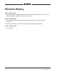
Revision History Issue 3, March 2016: 1. Documents new configuration that allows the party-line active detection function to be disabled (added to application firmware version 3.1). Issue 2, August 2015: 1. Documents enhanced unit identification feature (added to application firmware version 2.5). 2. Adds improvements to IP address configuration assignment explanation. Issue 1, January 2015: 1. Initial release. Issue 3, March 2016 Page 4 Model 45DC User Guide Studio Technologies, Inc.
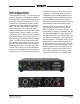
Introduction The Model 45DC Dante™ to Dual Party-Line Intercom Interface is designed for applications that utilize single-channel analog party-line (PL) intercom technology. The unit provides two independent single-channel interfaces that each support one party-line audio channel. Single-channel party-line intercom systems are commonly used in theater, entertainment, and education applications where a simple, reliable, low-cost, and easy to use solution is desired.
can also connect with one or two existing powered and terminated intercom circuits. Audio level meters provide confirmation of system performance during setup and operation. Support for transporting call light signals between Model 45DC units is also provided. Standard connectors are used for partyline intercom, Ethernet, and DC power interconnections. The Model 45DC’s enclosure has a “1/2-rack” 1U form factor and weighs less than two pounds, making it well suited for use in portable applications.
remain stable. This unique feature makes certain that objectionable audio signals, including oscillations and “squeals,” won’t be sent to other Dante-enabled devices. A significant capability of the Model 45DC’s two party-line intercom interfaces is their ability to supply DC power and 200 ohm AC terminations to “create” two independent intercom circuits. The 28 volt DC output can power user devices such as beltpacks.
throughout, providing low-distortion, lownoise, and high headroom. Using passive and active filters the frequency response of the audio channels is limited to nominally 100 Hz to 8 kHz. This range was selected to provide excellent performance for human speech while maximizing the ability of the hybrid circuits to create substantial “nulls.” Audio Meters The Model 45DC contains two sets of 5-segment LED level meters.
using a Neutrik etherCON RJ45. If Powerover-Ethernet (PoE) is available operation will commence immediately. An external 12 volt DC power source can also be connected by way of a 4-pin XLR. Partyline intercom connections are made using two 3-pin male XLR connectors. The Model 45DC is housed in a rugged yet lightweight aluminum enclosure that is designed to be “field tough.” It can be used as a standalone portable unit, supporting what’s known in the broadcast world as “throw-down” applications.
or placement in a semi-permanent location. Installed on the bottom of the chassis are screw-on “bump on” protectors (also known as “rubber feet”). These are useful if the unit is going to be placed on surfaces where scratching of either the Model 45DC or the surface material could take place. The “feet” can be removed, without the use of a tool, when rack- or custom-mounting the unit. 28 of the LEDs protrude through the front panel without interference.
(PoE) is preferred as it will provide operating power for the Model 45DC. To support PoE switch (PSE) power management the Model 45DC will enumerate itself as a PoE class 3 device. If PoE is not available an external 12 volt DC power source can be connected. This will be discussed in the next section of this guide. The 100BASE-TX Ethernet connection is made by way of a Neutrik etherCON protected RJ45 connector that is located on the back panel of the Model 45DC.
sources each have a maximum current of 150 mA. This modest amount of power can be very useful but requires that the type and number of connected user devices be selected appropriately. Many entertainment applications use the legacy Clear-Com RS-501 beltpack and each Model 45DC intercom circuit can directly support up to three of them. With the newer and more energy efficient Clear-Com RS-701 it should be possible to connect up to five of them.
Party-Line Active Detection Function When local power has been selected for a Model 45DC party-line interface and switch SW2 is in its off (down) position a minimum of approximately 5 mA of current must be drawn from that interface for an “active” condition to be recognized. When this condition is met the associated active LED on the front panel will light and the Dante output audio path will be active.
audio receiver (input) and audio transmitter (output) channels must be routed. The configuration settings will be stored in nonvolatile memory within the Model 45DC’s circuitry. The Model 45DC uses the Ultimo 2-input/2-output integrated circuit to implement the Dante architecture. This dictates which parameters can be configured and what choices are available.
Operation At this point the Model 45DC should have its party-line and Ethernet connections made. Depending on the application an external 12 volt DC power connection may have also been made. The Dante receiver (input) and transmitter (output) channels should have been routed using the Dante Controller software application. Normal operation of the Model 45DC can now begin. Initial Operation The Model 45DC will begin functioning a few seconds after its power source is connected.
How to Identify a Specific Model 45DC The Dante Controller software application offers an identify command that can be used to help locate a specific Model 45DC. When identify is selected for a specific unit its meter LEDs will light in a unique pattern. In addition, the SYS and SYNC LEDs, located directly below the etherCON connector on the back panel, will slowly flash green.
system this problem could be due to an incorrect configuration having been made to a specific channel or port. For example, the RTS ADAM system has a published nominal level of +8 dBu, but it’s not clear how this translates into a digital audio level on an associated Dante channel. Using its configuration software it’s most likely possible to set the nominal level of intercom key panels or ports to something different than +8 dBu.
mode is simple, only requiring the audio null pushbutton switch of the desired interface channel to be pressed and held for two seconds. The mode will change and the local power LED will display accordingly. The button can then be released. The selected operating mode for each interface channel will be stored in nonvolatile memory so that they will restore after a power-down/power-up cycle.
External Party-Line Circuit Operation When an interface channel’s local power LED is not lit that interface is intended to be connected to an external party-line circuit. The external circuit must provide power and termination impedances to “create” the party-line, with the Model 45DC simply serving as a user device. When connected to an external party-line circuit the active LED associated with that interface channel will light when the voltage on pin 2 is equal to or greater than approximately 18.
are actively using connected party-line intercom devices. The tones sent to the party-line circuit during the nulling process are not excessively loud or obnoxious, but most users might want to remove their headsets during the process. In addition to warning users, it’s a good idea to ask them to mute any active microphones. Muting the microphones can be significant as obtaining a “deep” null requires that no extraneous signals be present on the intercom circuit.
45DC’s Dante connection shouldn’t be a problem as a digital audio path that has a 48 kHz sample rate can easily transport a 20 kHz signal. null as was as keeping the 20 Hz call signal from each party-line audio path. When the Model 45DC detects DC on the audio path (pin 3 of the back-panel interface connector) it will digitally generate a 20 kHz tone and mix (sum) it with any audio signals present on the associated Dante transmitter (output) channel.
interconnection, separate crimp terminals are attached to three loose wires and then “snapped” into the housing. Molex part number 08-50-0114 specifies crimp terminals that are appropriate for 22 to 30 gauge wires. These terminals are available worldwide from sources such as Digi-Key (www.digikey.com). IP Address Assignment By default the Model 45DC’s Ethernet interface will attempt to obtain an IP address and associated settings using DHCP (Dynamic Host Configuration Protocol).
ranges from 1 through 5. Refer to Figure 5 for a detailed view of the LEDs and the corresponding application firmware version numbering scheme. The Model 45DC’s initial application firmware release is version 2.2 which is represented by the second from the bottom LED of each column being lit. Major Release Number Release Sub-Number O 4 .4 O O 3 .3 O 2 .2 O 1 .1 O Figure 5. Detail of front panel showing the status LEDs that display the application firmware version.
3. Remove power from the Model 45DC. Ultimo Firmware Update 4. Insert the prepared USB flash drive into the Model 45DC’s USB port, located on the back panel of the unit. As previously discussed in this guide, the Model 45DC implements Dante connectivity using the Ultimo integrated circuit from Audinate. This 2-input/2-output device can be updated by way of the Model 45DC’s Ethernet connection. The latest Dante firmware file is available on the Studio Technologies website.
Specifications Power Sources: Power-over-Ethernet (PoE): class 3 (mid power) per IEEE 802.3af External: 10 to 18 volts DC, 1.