
Datasheet


Studio Technologies, Inc. Model 400 SDI-Over-Fiber Transport System, Issue 3, Page 2
Model 400 Specifications
Ethernet Interface:
Type: 10/100, auto MDI/MDI-X
Connector: RJ45 (8-pin modular)
Status LEDs: 2, link and activity
Supported Protocols: HTTP, SNMP, DHCP, DNS
Display: vacuum fluorescent (emissive) with color
LED backlighting
Power Inputs:
AC Mains: 100 to 240 V, 50/60 Hz, 24 W max,
varies by configuration
AC Mains Connector: 3-blade, IEC 320 C14-
compatible (mates with C13)
DC: 10 to 18 V, 1.6 A max, varies by configuration
DC Connector: 4-pin male XLR-type
Dimensions (Overall):
19.00 inches wide (48.3 cm)
1.72 inches high (4.4 cm)
11.50 inches deep (29.2 cm)
Mounting: one space (1U) in a standard 19-inch
rack
Weight: 5.5 pounds (2.5 kg)
SDI Inputs:
Quantity: up to 12, in groups of three depending
on ordered configuration
Data Rate: 270 Mb/s to 2.97 Gb/s
Supported Standards: 3G-SDI (SMPTE 424M),
HD-SDI (SMPTE 292), SD-SDI (SMPTE 259M),
DVB-ASI (AES3 digital audio transport not
supported)
Connector: BNC, 3G-SDI optimized, gold plating
on center pin, per IEC 61169-8 Annex A
Type: unbalanced
Impedance: 75 ohms
SDI Loop-Through Outputs:
Quantity: one associated with each SDI input
Source: re-clocked copy of input
Data Rate: 270 Mb/s to 2.97 Gb/s
Supported Standards: 3G-SDI, HD-SDI, SD-SDI,
DVB-ASI
Connector: BNC, 3G-SDI optimized, gold plating
on center pin, per IEC 61169-8 Annex A
Type: unbalanced
Impedance: 75 ohms
Level: 800 mV p-p, nominal
Optical Outputs:
Quantity: up to four, depending on ordered
configuration
Compliance: SMPTE 297 (as applicable)
Fiber Type: single-mode
Connector: ST PC (SC optional)
Multiplexed Wavelengths: 1310 nm (FP), 1490 nm
(DFB), 1550 nm (DFB)
Launch Power: –3 dBm nominal @ 1310 and
1550 nm; –1 dBm nominal @ 1490 nm
Typical Fiber Length: 10 km minimum
Optical Inputs:
Quantity: up to four, depending on ordered
configuration
Studio Technologies, Inc.
Skokie, Illinois USA
+1 847-676-9177
© by Studio Technolog
ies, Inc., May 2013
www.studio-tech.com
Compliance: SMPTE 297 (as applicable)
Fiber Type: single-mode
Connector: ST PC (SC optional)
Wavelengths Supported: 1310 nm, 1490 nm, and
1550 nm
Receive Sensitivity: –17 dBm, nominal @ 2.97 Gb/s
Maximum Input Power: –3 dBm, nominal
Digital Video Outputs:
Quantity: up to 24 (organized as 12 pairs),
depending on ordered configuration
Data Rate: 270 Mb/s to 2.97 Gb/s
Supported Standards: 3G-SDI, HD-SDI, SD-SDI,
DVB-ASI
Connector: BNC, 3G-SDI optimized, gold plating
on center pin, per IEC 61169-8 Annex A
Type: unbalanced
Impedance: 75 ohms
Level: 800 mV p-p, nominal
Specifications subject to change without notice.
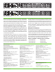
Model 400-12T Back Panel
If both AC and DC power sources are connected to a Model 400,
the unit will be powered by the AC mains supply. Only if the AC
mains source fails will a load be placed on the DC source. This
allows a source of DC, typically a battery pack, to serve in a backup
capacity. With this arrangement normal SDI-over-fiber transport
operation can continue even if AC mains power is lost.
Remote Monitoring and Configuration
The Model 400 has an embedded web server that allows the user
to monitor system status through any web-enabled device such
as a personal computer or smartphone. System status can also
be communicated using SNMP, making it possible to integrate
the unit’s monitoring information into a networked alarm and
control software application.
The Model 400’s status screen lets a user or supervisor check for
the presence of AC and DC power sources as well as individual
SDI input channel status, signal rate, and whether the optical
transmitters are enabled. The optical output power of each
electrical-to-optical (E2O) channel is reported directly in dBm. The
optical receive power (in dBm) of each optical-to-electrical (O2E)
channel is also displayed. This is a particularly useful feature for
remote system troubleshooting.
The embedded web server also provides a configuration menu
allowing a variety of monitoring parameters to be set. These
include alarms for loss of AC or DC power, over-temperature, and
low optical transmit and receive levels. Additional menu screens
provide access to SNMP, network IP address, and front-panel
display configurations. Advanced features include the ability
to remotely update the Model 400’s system firmware via the
Ethernet connection.
Simple Installation
While the Ethernet-accessed monitoring and configuration func-
tions enhance the utility of the Model 400 they are not necessary
for SDI-over-fiber transport operation. Model 400 units will deliver
reliable, high-quality performance with no other user actions
except for making SDI-over-coaxial cable, fiber, and power con
-
nections. All back-panel connectors are clearly labeled for simple,
fast, and intuitive use. And the front-panel display provides direct
access to the unit’s most important status information.
Model 400-12R Back Panel
• Model 400-6T/6R
• Model 400-9T/3R
• Model 400-3T/9R
Other available configurations include:
• Model 400-6T
• Model 400-6R
• Model 400-3T/3R