Model 391 Dante Alerting Unit User Guide Issue 2, December 2018 This User Guide is applicable for serial numbers M391-00151 and later with application firmware 1.2 and later and Dante® firmware 4.4.0 (UltimoX2 4.1.4.2) and later Copyright © 2018 by Studio Technologies, Inc., all rights reserved www.studio-tech.
This page intentionally left blank.
Table of Contents Revision History ............................................................ 4 Introduction ................................................................... 5 Getting Started .............................................................. 8 Dante Configuration ...................................................... 9 Model 391 Configuration .............................................. 10 Operation ...................................................................... 14 Technical Notes .
Revision History Issue 2, December 2018: 1. Documents new feature which allows simultaneous call detection on channels 1 and 2. 2. Documents expanded frequency detection range for call signals. (Was 20 kHz, now 18-23 kHz nominal.) Issue 1, May 2018: 1. Initial release. Issue 2, December 2018 Page 4 Model 391 User Guide Studio Technologies, Inc.
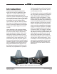
Introduction The Model 391 Dante® Alerting Unit builds on the limited capabilities of the “beacon” or “strobe” devices that are ubiquitous with analog party-line (PL) intercom systems and adds a broad range of new and enhanced features. The Model 391 responds to audio “call” signals that are present in the unit’s Dante audio input channels. With an 18-23 kHz detection range, it will detect tone call signals that are commonly utilized in both legacy analog and modern digital PL intercom circuits.
Applications The most-typical application for the Model 391 is to alert users that a call signal on an intercom channel is active. Some technicians and engineers associated with theater, entertainment, and corporate events won’t always stay “on headset” and may need to be alerted when their presence on the production’s intercom system is needed. As an example, a front-of-house audio mixer could find value by placing a Model 391 unit on their audio console or associated equipment rack.
The Model 391 includes an audio sounder whose output will “cut through” ambient audio to gain the attention of nearby personnel. The character of the sounder was selected to be effective at gaining attention rather than being pleasant. The overall level range of the sounder can be configured while the precise value can be set by the user by way of a rotary potentiometer. The action of the sounder can be configured from among multiple choices, including continuous, beep, and pulse.
standard. This allows fast and efficient interconnection with an associated data network. To support PoE power management, the Model 391’s PoE interface reports to the power sourcing equipment (PSE) that it’s a class 1 (very low power) device. If a PoE-enabled Ethernet port can’t be provided by the associated Ethernet switch a low-cost PoE midspan power injector can be utilized. Setup, Configuration, and Operation Setup, configuration, and operation of the Model 391 is simple.
or an etherCON protected RJ45 plug. If desired, the Model 391’s analog line-level output may be interfaced with other equipment using a cable terminated with a standard 3-pin female XLR connector. Ethernet Connection with PoE A 100BASE-TX Ethernet connection that supports Power-over-Ethernet (PoE) is required for Model 391 operation. This one connection will provide both the Ethernet data interface and power for the Model 391’s circuitry.
one audio source to be routed to the Model 391 while others may utilize both. The Model 391 supports an audio sample rate of 48 kHz with no pull-up/pull-down values available. While technically the Model 391 can serve as a clock master for a Dante network (as can all Dante-enabled devices) in virtually all cases the unit will be configured to receive “sync” from another device. The Model 391 has a default Dante device name of ST-M391 along with a unique suffix.
Active Mode Line Out Choices are: Mode 1 and Mode 2; also can disable access to Mode 2 Choices are: Off, On When Call Active, Always On–Ch 1, and Always On–Ch 2 This setting allows the operation of the line-level analog output to be configured. If On When Call Active is selected audio from the designed Call Source Dante receiver channel will be present on the line output whenever a call is detected. If the call function is not active then no audio will be present on the line output.
The default configuration for both Mode 1 and Mode 2 is On When Call Active. Note that the exact action of the visual indicator when it’s active will follow the Intensity, Action, and Color configuration parameters, described next in this guide. The Always On configuration can be useful for a number of purposes. One example is to make it easier to observe the action of the visual indicator as its intensity, action, and color configurations are selected.
the configuration of the Status configuration, it can be enabled whenever a call signal is present or could be active all the time.) When selected to Slow Flash the visual indicator will alternate between on and off two times per second. In Fast Flash the visual indicator will alternate between on and off a little more than four times per second. In the Pulse configuration the visual indicator will light twice followed by a short pause, repeating a little more once per second.
Action Choices are: Continuous, Slow Beep, Fast Beep, and Pulse Four Action choices allow the character of the audio sounder to be selected. Select the configuration that best fits the application. When selected for Continuous the audio sounder will be constant whenever it is active. When selected for Slow Beep the audio sounder will alternate between on and off twice per second. The Fast Beep pattern will cause the audio sounder to alternate between on and off a little more than four times per second.
Initial Operation The Model 391 will start to function as soon as a Power-over-Ethernet (PoE) power source is connected. However, it may take 20 to 30 seconds for full operation to commence. Upon initial power up the three status LEDs, located on the back panel below the RJ45 jack, will begin to light as network and Dante connections are established.
A configuration choice within STcontroller allows disabling access to operating Mode 2. If this feature is enabled and the pushbutton switch is pressed and held the Mode 1 LED will remain lit while the Mode 2 LED will quickly flash four times to indicate that access to it has been disabled. Visual Alert As expected, the action of the Visual Alert section will follow the configuration choices made for the operating mode that has been selected.
Line Output What is present on the line output connection will depend on the configuration settings associated with the active Model 391 operating mode. Some applications will have no audio present on the line output. Other configurations will have audio from Dante receiver channel 1 or channel 2 present at all times on the line output. In other cases audio will be present on the line output only when a call signal is being received.
Optimizing Network Performance For best Dante audio-over-Ethernet performance a network that supports VoIP QoS (voice-over-internet-protocol quality of service) capability is recommended. This can typically be implemented on virtually all contemporary managed Ethernet switches. There are even specialized switches that are optimized for entertainment-associated applications. Refer to the Audinate website (www.audinate.com) for details on optimizing networks for Dante applications.
The update process begins by preparing a USB flash drive. The flash drive doesn’t have to be empty (blank) but must be in the personal-computer-standard FAT32 format. Save the new firmware file in the root directory with a name of m391.bin. Studio Technologies will supply the application firmware file inside a .zip archive file. While the firmware file inside of the zip file will adhere to the naming convention required by the Model 391, the name of the zip file itself will include the file’s version number.
7. Confirm that the desired firmware version has been correctly loaded. This can be done by pressing and holding the operating mode button, applying power to the Model 391, and then “reading” the application firmware version number by observing the visual indicator. Alternately, the STcontroller application can be used to identify the application firmware version number. Whatever method you use, ensure that the desired version is present. 8.
Specifications Power Source: Power-over-Ethernet (PoE): class 1 (very low power, ≤3.
Appendix A STcontroller default Model 391 configuration values: Active Mode: Mode 1 Disable Mode 2: Box not checked Mode 1: Call Source: Channel 1 Line Out: On When Call Active Visual Alert – Status: On When Call Active Visual Alert – Minimum On Time: Follow Call Visual Alert – Intensity: High Visual Alert – Action: Continuous Visual Alert – Color: Green Audio Alert – Status: Low Range Audio Alert – Action: Continuous Audio Alert – On Delay: Follow Call Mode 2: Call Source: Channel 1 Line Out: On When Call A