
Manual


Issue 2, August 2019 Model 371A User Guide
Page 8 Studio Technologies, Inc.
MODEL 371A
INTERCOM BELTPACK
located on the bottom of the Model 371A’s
enclosure. An Ethernet data connection
with Power-over-Ethernet (PoE) capability
will be made using either a standard RJ45
patch cable or an etherCON protected
RJ45 plug. A headset that has a cable-
mounted 4-pin female XLR connector will
be plugged into the Model 371A’s 4-pin
male headset connector.
Ethernet Connection with PoE
A 100BASE-TX Ethernet connection that
supports Power-over-Ethernet (PoE) is re-
quired for Model 371A operation. This one
connection will provide both the Ethernet
data interface and power for the Model
371A’s circuitry. A 10BASE-T connection is
not sufficient and a 1000BASE-T (“GigE”)
connection is not supported unless it can
automatically “fall back” to 100BASE-TX
operation. The Model 371A supports Eth-
ernet switch power management, enumer-
ating itself as a PoE class 1 device. Any
source that is compliant with the IEEE®
802.3af standard will function correctly.
Should the selected Ethernet switch port
support Energy-Efficient Ethernet (EEE) it
must be disabled to help ensure reliable
Dante operation.
The Ethernet connection is made by way
of a Neutrik etherCON protected RJ45
receptacle that is located on the bottom of
the Model 371A’s enclosure. This allows
connection by way of a cable-mounted
etherCON connector or a standard RJ45
plug. The Model 371A’s Ethernet interface
supports auto MDI/MDI-X so that a cross-
over cable will never be required.
Headset Connection
The Model 371A provides a 4-pin male
XLR connector that interfaces with the
microphone and headphone connections
of an intercom or broadcast-style headset.
Refer to Figure 2 for connection details.
The microphone input connections are
compatible with most unbalanced dynamic
or electret (low-voltage DC-powered)
microphones. A balanced dynamic micro-
phone should, in most cases, also function
correctly if its signal – (low) is connected to
Model 371A’s mic in –/shield connection.
No support is provided for microphones
that require P12 or P48 phantom power.
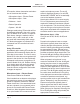
In most cases headsets associated with
single-channel party-line intercom sys-
tems will be directly compatible. A mon-
aural (single-ear or “single-muff”) headset
should be wired such that its –/shield/
screen lead is connected to pin 3 and its
+ lead is connected to pin 4. To allow us-
ers of stereo (dual-ear or “double-muff”)
headsets to hear the Model 371A’s head-
phone output in both ears requires that
both its –/shield/screen leads be connect-
ed to pin 3 and both its + leads be con-
nected to pin 4.
Figure 2. Headset connection pinout chart
Dante Configuration
For audio to pass to and from the Model
371A requires that several Dante-related
parameters be configured. These configu-
ration settings will be stored in non-volatile
memory within the Model 371A’s circuitry.
Configuration will typically be done with the
Dante Controller software application which