
Manual
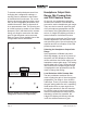
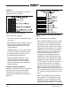
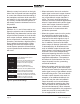
Table Of Contents

Model 216 User Guide Issue 5, November 2017
Studio Technologies, Inc. Page 19
and audio input channel 4 is assigned
to the right headphone output channel.
The level of audio inputs 3 and 4 is con-
trolled by rotary level control C3, located
on the right side of the front panel. The
sidetone function will not be active.
Headphone Minimum Level
Switch 9 is used to configure the head
-
phone output’s minimum level. In the
–40 dB setting the minimum headphone
output level is approximately 40 dB below
maximum. The headphone output will nev-
er fully mute. This ensures that any audio
signal present on the assigned audio input
channels (1 and 2 or 1, 2, 3, and 4) will
always be present on the headphone out-
put. In most on-air broadcast applications
this is the appropriate setting, ensuring the
some level of signal is always present.
When full mute is selected moving any
level control to its fully counterclockwise
position will cause its associated chan-
nel to fully mute. If a rotary level control is
set to serve as a balance control, moving
it to either fully counterclockwise or fully
clockwise position will cause the associ-
ated signal to fully mute. Selecting the full
mute mode may be appropriate for ap-
plications where minimizing the chance of
audio “leakage” is important. This could
occur when the connected headset or
headphones are at times placed on a desk
or tabletop.
audio inputs 1 and 2 are controlled by
rotary level control C1, located on the
left side of the front panel. The balance
(relative level) of both these signals is
controlled by rotary level control C2,
located in the center of the front panel.
Sidetone audio is assigned to both the
left and right headphone output chan-
nels and its level is controlled by rotary
level control C3, located on the right
side of the front panel. Audio inputs 3
and 4 are not used.
• SW7 Off (Down)/SW8 On (Up): Audio
input channel 1 is assigned to both the
left and right headphone output chan-
nels. The level of the signal being sent
to both channels is controlled by rotary
level control C1, located on the left side
of the front panel. Audio input channel
2 is assigned to both the left and right
headphone output channels. The level
of the signal being sent to both chan-
nels is controlled by rotary level control
C2, located in the center of the front
panel. Audio input channel 3 is assigned
to the left headphone output channel
and audio input channel 4 is assigned
to the right headphone output channel.
The level of audio inputs 3 and 4 is con-
trolled by rotary level control C3, located
on the right side of the front panel. The
sidetone function will not be active.
• SW7 On (Up)/SW8 On (Up): Audio input
channel 1 is assigned to the left head-
phone output channel and its level is
controlled by rotary level control C1, lo-
cated on the left side of the front panel.
Audio input channel 2 is assigned to the
right headphone output channel and its
level is controlled by rotary level control
C2, located in the center of the front
panel. Audio input channel 3 is assigned
to the left headphone output channel
Figure 8. Headphone minimum level switch
settings