
Manual
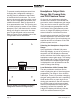
Table Of Contents

Issue 5, November 2017 Model 216 User Guide
Page 12 Studio Technologies, Inc.
Headphone Output
The Model 216’s headphone output is
compatible with stereo or mono head-
phones, headsets, or earpieces. Connect-
ing devices with a nominal impedance
of 100 ohms or greater is preferred. This
shouldn’t prove to be an issue since es-
sentially all of the contemporary devices
meet this recommendation.
Devices are connected to the headphone
output by way of a ¼-inch 3-conductor
phone jack located on the Model 216’s
back panel. As is standard for stereo
headphones, the left channel is connected
to the tip lead of the ¼-inch headphone
jack. The right channel is connected to
the ring lead of the jack. Common for both
channels is connected to the sleeve lead.
Devices with ¼-inch 2-conductor “monau-
ral” plugs can also be used with the Model
216’s headphone output. In this arrange-
ment only the tip lead (left channel) will
be active. The 2-conductor plug will physi-
cally connect (“short”) the ring lead (right
channel) to the sleeve lead (common).
Technically this won’t damage the circuitry
associated with the right-channel head-
phone output since 10 ohm protection
resistors are electrically in series with the
headphone output circuits.
Ethernet Connection
An Ethernet connection that supports
100BASE-TX is required for the Model
216’s Dante Audio-over-Ethernet con-
nectivity. A 10BASE-T connection is not
sufficient for Model 216 operation. A
1000BASE-T (“GigE”) connection is not
supported unless it can automatically
“fall back” to 100BASE-TX operation. An
Ethernet connection that supports Power-
over-Ethernet (PoE) is preferred as it will
provide operating power for the Model
216. For Ethernet with PoE switch (PSE)
power management the Model 216 will
enumerate itself as a PoE class 2 device.
If PoE is not available an external 12 volt
DC power source can also be connected.
This will be discussed in the next section
of this guide.
The 100 Mb/s twisted-pair Ethernet con-
nection is made by way of a Neutrik ether-
CON protected RJ45 connector that is
located on the back panel of the Model
216. This allows connection by way of a
cable-mounted etherCON plug or a stan-
dard RJ45 plug. The Model 216’s Ethernet
interface supports auto MDI/MDI-X so
that most cabling implementations will be
directly supported.
External 12 Volt DC Input
An external source of 12 volts DC can
be connected to the Model 216 by way
of the 4-pin male XLR connector which
is located on the back panel. While the
requirement for the external source is
nominally 12 volts, correct operation will
take place over a 10 to 18 volt range. The
Model 216 requires 270 milliamperes at
12 volts DC for correct operation. The DC
source should be terminated to a 4-pin
female XLR connector with pin 1 negative
(–) and pin 4 positive (+). Purchased as
an option, the PS-DC-02 power supply is
available from Studio Technologies. Its
AC mains input allows connection to 100-
240 volts, 50/60 Hz and its 12 volt DC,
1.5 amperes maximum output is terminat-
ed on a 4-pin female connector.
As previously discussed in this guide, an
Ethernet connection that provides Power-
over-Ethernet (PoE) can serve as the
Model 216’s power source. Alternately,
an external 12 volt DC source can be