
Manual
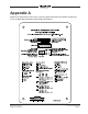

Table Of Contents

Issue 5, December 2018 Model 215 User Guide
Page 34 Studio Technologies, Inc.
Appendix B
The following list provides details on the 3-pin header connectors located on the Model
215’s printed circuit board. Shown are both reference numbers and associated functions.
P2: Microphone Input
Pin 1 common
Pin 2 high (+)
Pin 3 low (–)
P3: External 12 Volt DC Input
Pin 1 – DC
Pin 2 + DC
Pin 3 not used
P5: Headphone Output
Pin 1 common
Pin 2 left channel (tip)
Pin 3 right channel (ring)
P6: DC Output
Pin 1 common
Pin 2 10-18 volts DC out
Pin 3 not used
P7: Relay Contact 1
Pin 1 common
Pin 2 normally open
Pin 3 normally open
Note: Pins 2 and 3 close (short) when
main pushbutton is active.
P8: Relay Contact 2
Pin 1 common
Pin 2 normally open
Pin 3 normally open
Note: Pins 2 and 3 close (short) when
talkback 1 pushbutton is active.
P10: Contact Closure Input – Main and
Talkback 1
Pin 1 common
Pin 2 main pushbutton
Pin 3 talkback 1 pushbutton
P11: Contact Closure Input – Talkback 2
Pin 1 common
Pin 2 not used
Pin 3 talkback 2 pushbutton