User Guide Issue 5, December 2018 This User Guide is applicable for serial numbers: M215-00151-02000 with application firmware 2.3 and later and Dante® firmware 2.6.1 (Ultimo 4.0.10.2) and later or M215-02001-later with application firmware 2.3 and later and Dante firmware 4.4.1 (UltimoX4 4.1.4.2) and later Copyright © 2018 by Studio Technologies, Inc., all rights reserved www.studio-tech.
This page intentionally left blank.
Table of Contents Revision History ............................................................ 4 Introduction ................................................................... 5 System Features ........................................................... 5 Installation ..................................................................... 11 Configuration ................................................................ 13 Dante Configuration ......................................................
Revision History Issue 5, December 2018: 1. Documents the new tally tone feature (added in application firmware 2.3). Issue 4, July 2017: 1. Documents that the unit now supports the STcontroller software application. 2. Documents the new configurable headphone output gain range feature. Issue 3, March 2017: 1. Documents revised headphone operating mode choices (revised in application firmware 1.3). Issue 2, September 2015: 1. Documents enhanced unit identification feature. 2.
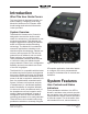
Introduction What This User Guide Covers This User Guide is designed to assist you when installing, configuring, and using Model 215 Announcer’s Consoles. Additional background technical information is also provided. System Overview The Model 215 Announcer’s Console is designed to serve as the audio control center for announcers, commentators, and production personnel. This tabletop unit supports applications utilizing the Dante® audio-over-Ethernet media networking technology.
other primary uses. Two LEDs display the on/off status of the main output. Two additional pushbutton switches control the status of the talkback output channels. These are the audio signals used to communicate with producers, directors, spotters, or other behind-the-scenes production personnel. A status LED is associated with each of the talkback pushbuttons. The pushbutton switches use gold-plated contacts for reliable long-term operation and include backlighting using white LEDs.
A large part of the Model 215’s unique power is the ability to configure the operation of the main and talkback functions. To meet the needs of the many specific broadcast and production applications, a variety of pushbutton operating modes are available. The main pushbutton can be selected to operate from among four modes. In the “push-to-mute” mode the pushbutton performs a momentary mute of the audio signal associated with the main output channel.
rotary controls adjust the four Dante input channels and the sidetone audio signals. The first two modes support standard onair applications and use Dante audio input channels 1 and 2. In the broadcast world these two signals are often referred to as talent cue or IFB audio. In live television applications they typically originate in production trailers or control rooms and provide one channel of program-withinterrupt audio and a second channel with program-only audio.
minimum (fully-counterclockwise) position. When the level control on the right side is used for sidetone it will always allow the sidetone signal to be fully muted. The headphone output was designed to meet the needs of contemporary headphones and headsets. Specifically, the output circuits act as voltage drivers rather than power drivers. In this configuration they can provide high output levels with very low distortion and noise, along with minimal current consumption.
status of the network connection, PoE power source, and Dante interface. Configuration and Flexibility Model 215 configuration settings can be made using twelve DIP switches and two pushbutton switches. The STcontroller software application can be used to view and change the gain of the microphone preamplifier, the on/off status of P48 phantom power, and the headphone output gain range.
set of features the other products in the 200-Series should be reviewed. Complete information is available on the Studio Technologies website. Installation In this section signal interconnections will be made using the connectors located on the back panel of the Model 215. A microphone signal will be interfaced by way of a 3-pin XLR connector. A ¼-inch 3-conductor phone jack is provided for the headphone output.
Headphone Output The Model 215’s headphone output is compatible with stereo or mono headphones, headsets, or earpieces. Connecting devices with a nominal impedance of 100 ohms or greater is preferred. This shouldn’t prove to be an issue since essentially all of the contemporary devices meet this recommendation. Devices are connected to the headphone output by way of a ¼-inch 3-conductor phone jack located on the Model 215’s back panel.
source can be connected at the same time. If both PoE and an external 12 volt DC source are connected, power will be drawn only from the PoE supply. If the PoE source becomes inoperative the 12 volt DC source will provide the Model 215’s power with no interruption in operation. Pushbutton Labeling The three pushbutton switches used in the Model 215 were selected for several reasons.
the security panel provides a summary of the configurable parameters and related information. Refer to Appendix A for a representative view. The security panel is held in place by means of four rubber bumpers (“feet”) that have built-in screws. Using your fingers, remove the four bumpers so that the panel can be removed. Refer to Figure 2 for a detailed view of the configuration switch assemblies.
Selecting the correct amount of gain for an application might take a little experimentation. The goal is to bring the mic’s signal up to the Dante reference level which is typically considered to be –20 dBFS. (This is 20 dB below digital maximum.) Operating at this signal level will help ensure the delivery of “clean” audio to the destination device or devices. There’s no “perfect” gain setting that this guide can recommend.
headphone output gain range. The application is available for download on the Studio Technologies website (www.studiotech.com). Its initial release is compatible with the Windows® operating system. Changes made using the application will be displayed in real-time on the Model 215’s 2-digit display. Changes made to the mic preamp gain, P48 on/off status, and headphone output gain range using the Model 215’s pushbutton switches will be displayed in STcontroller.
• Push to Talk: In this mode the audio signal on the main output channel is normally muted. The main audio signal will become active whenever the pushbutton is pressed and held. • Latching: In this mode the audio signal on the main output channel will change between its active and muted states whenever the pushbutton is pressed. Upon power up the audio signal on the main output will be in its muted state. • Hybrid: This mode is a combination of push to talk and latching action.
Sidetone Switches SW1-5 and SW1-6 configure the way the sidetone function operates. Figure 6. Sidetone switch settings Four modes are available: Figure 7. Headphone operating mode switch settings • Off: In this mode the sidetone function not active. There are four choices available: • Main Button: In this mode the sidetone function will be active whenever the audio signal is present on the main output channel.
rotary level control C1, located on the left side of the front panel. The balance (relative level) of both these signals is controlled by rotary level control C2, located in the center of the front panel. Sidetone audio is assigned to both the left and right headphone output channels and its level is controlled by rotary level control C3, located on the right side of the front panel. Audio inputs 3 and 4 are not used.
When the rotary level control on the right side of the front panel has been assigned to control the sidetone level the setting of the headphone minimum level mode will not impact it. In this case when the control is in its fully counterclockwise position it will always cause the sidetone level to be fully muted. System Mode Switches SW1-11 and SW1-12 are used to configure the overall operating mode of the Model 215.
duced in level or attenuated) by 18 dB whenever the main or talkback output channels have audio present. In this way the three output channels can be used independently, with none impacting the other. And, the headphone output can be connected to amplified loudspeakers. The speakers will reduce in level whenever one of the output channels is active, preventing acoustical feedback.
Controller application but in most applications 48 kHz will be appropriate. The Model 215 can serve as the clock master for a Dante network but in most cases that would not be optimal. Operation At this point the audio, Ethernet, and power connections should have been made. The pushbutton labels may have been revised. The desired configuration should have be made using the pushbutton and DIP switches.
with the main pushbutton switch may be lit. The user is now presented with three pushbutton switches, four LEDs, and three rotary controls. These are simple to operate and understand, as will be described in later paragraphs. Ethernet, PoE, and Dante Status LEDs Four status LEDs are located below the etherCON connector on the Model 215’s back panel. The LINK/ACT LED will light green whenever an active connection to a 100 Mb/s Ethernet network has been established.
backlit using white LEDs. The intensity (brightness) of the LEDs is configured from a choice of two values, low or high. The backlighting does not provide an indication of the associated pushbutton’s status nor do they serve as a tally function, but rather allow the pushbutton’s labeling and location to be visible in low-light conditions. Main Button and LED Indicators The pushbutton on the left, factory labeled as COUGH, functions according to the selected configuration.
ed state. If the audio signal was in the “latched-on” state when talkback activity began, once talkback activity ends that state will resume; the audio signal associated with the main output channel will again be in its on (“latched”) state. Talkback Buttons and LED Indicators The pushbutton in the middle, factory labeled TALKBACK 1, controls the audio signal associated with the talkback output channel 1.
The user, in response to a changing operating environment, can then move the level controls to get more or less level as desired. The detent position will always remain as a useful reference point. To achieve this condition the audio level on the appropriate audio inputs will have to be calibrated as required. This is somewhat counter intuitive to the usual mentality of just providing the user with whatever level comes up by default.
way multiple Dante-enabled devices can be connected together and automatically function, whether or not a DHCP server is active on the LAN. Even two Dante-enabled devices that are directly interconnected using an RJ45 patch cord will correctly acquire IP addresses and be able to communicate and transport audio. capability is recommended. This can typically be implemented on virtually all contemporary managed Ethernet switches.
Additional Connectors Locations Two spare connector locations are provided on the Model 215’s back panel. They are labeled A and B. From the factory they contain blank plates that can be readily removed and replaced with a variety of “XLR style” connectors. The spare connector locations are specifically included so that a Model 215 can be customized to meet the many specific needs that arise in broadcast and related audio applications.
terminals are attached to three loose wires and then “snapped” into the housing. Molex part number 08-50-0114 specifies crimp terminals that are appropriate for 22 to 30 gauge wires. These terminals are available worldwide from sources such as Digi-Key (www.digikey.com). To make the process of connecting to the Model 215’s headers a simple task an interface cable kit, part number 31087, is available from Studio Technologies. Each kit includes five cable assemblies and a length of heat-shrinkable tubing.
Pushbutton Backlighting From the factory, white LEDs are installed in the pushbutton housings. These LEDs provide illumination (“backlighting”) of the pushbutton switches. This may prove useful for applications where adequate room lighting is not available. It’s important to note that the pushbutton lighting does not provide a tally function; it is intended to illuminate the pushbutton’s clear lens and associated labeling.
2. Ensure that nothing is present in the USB port. Then again apply power to the unit and “read” the currently loaded firmware version using the 2-digit LED display. Note this for later reference. 3. Remove power from the Model 215. 4. Insert the prepared USB flash drive into the Model 215’s USB port, located on the back panel of the unit. 5. Apply power to the Model 215.
Specifications Power Sources: Power-over-Ethernet (PoE): class 2 (low power) per IEEE 802.3af External: 10 to 18 volts DC, 270 mA max @ 12 volts DC Network Audio Technology: Type: Dante audio-over-Ethernet Bit Depth: up to 24 Sample Rates: 44.
Appendix A Attached to the bottom of the unit is a security panel with text that provides a summary of the configurable parameters and related information. Model 215 User Guide Studio Technologies, Inc.
Appendix B The following list provides details on the 3-pin header connectors located on the Model 215’s printed circuit board. Shown are both reference numbers and associated functions.