
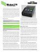
Datasheet


The first mode can be used to support traditional on-air sports
applications. In this mode it would be typical to feed (connect)
program-with-interrupt audio to the channel 1 audio input and
program-only audio to the channel 4 audio input. Rotary control
C1, located on the left side, is used to adjust the level of the
program-with-interrupt audio signal that’s routed to the left
headphone output channel. Rotary control C2, located in the
center, is used to adjust the level of the program-only audio
signal that’s routed to the right headphone output channel. For
use with dual-channel or stereo cue signals, another headphone
output mode provides a stereo (“level/balance”) mode. In this
mode rotary control C1 adjusts the level of both input channels 1
and 2, while rotary control C2 allows adjustment of the left/right
level balance. In both of these modes rotary control C3, located
on the right, is used to adjust the level of the side-tone audio
signal that is sent to both the left and right headphone output
channels.
In the third headphone output mode rotary control C1 adjusts
the level of the channel 1 input audio source before it is routed
to both the left and right headphone output channels. Rotary
control C2 adjusts the level of the channel 2 audio source before
it is routed to both the left and right headphone output channels.
Rotary control C3 adjusts the level of both the channel 3 and
channel 4 audio inputs which are then routed to, respectively,
the left and right headphone output channels.
The fourth headphone output mode is similar to the third with
the except that input 1 is routed only to the left headphone out
-
put channel while input 2 is routed only to the right headphone
output channel. Inputs 3 and 4 will function in the same way in
both modes 3 and 4.
The sidetone function allows audio from the Model 215’s micro
-
phone preamplifier to be routed to the headphone output. This
can be useful, providing the user with an aural confirmation of
the signal connected to the mic input. It is especially important
when a “mix-minus” talent cue signal is provided for the user. For
application flexibility the sidetone function can be configured from
among four choices, specifying when it will be active in relation
to the status of the main and talkback functions.
To help minimize the chance of broadcast cues being missed, the
action of the level controls can be configured so that there’s al
-
ways a minimum headphone output level. Alternately, the controls
can be configured to fully mute when they are at their minimum
(fully-counterclockwise) position. When the level control on the
right side is used for sidetone it will always allow the sidetone
signal to be fully muted.
The headphone output was designed to meet the needs of con
-
temporary headphones and headsets. Specifically, the output
circuits act as voltage drivers rather than power drivers. In this
configuration they can provide high output levels with very low
distortion and noise, along with minimal current consumption.
The output circuits can safely drive stereo or mono loads. This
ensures that all types of headphones, headsets, and earpieces
can be directly connected.
A configuration feature allows the headphone output gain range
to be selected. The low setting is appropriate for most applica
-
tions where users need to listen at moderate levels. The high
setting can be useful when monitoring at higher levels is war
-
ranted by an application.
Dante Audio-over-Ethernet
Audio data is sent to and from the Model 215 using the Dante
audio-over-Ethernet media networking technology. For flexibility
in meeting a variety of sonic requirements bit depths of up to 24
and sample rates of 44.1 and 48 kHz are supported.
Audio transmitter (output) and receiver (input) channels on as
-
sociated Dante-enabled devices can be assigned to the Model
215 using the Dante Controller software application. This makes
selecting the way in which the Model 215 fits into an application
a simple matter. For example, the main audio output channel
can be assigned to the input of an audio console. The talkback
audio output channels could be assigned to inputs on a matrix
intercom system. And the hot mic audio output channel could be
routed directly to an amplified speaker for producer or director
use. No special routing or “multing” using cables or patch points
is required to send the output channels to multiple destinations.
And a single mouse-click is all that’s required to reroute the
audio signals.
On the input side, the Model 215 allows up to four headphone cue
sources to be received from an audio console, matrix intercom
system, or a variety of other Dante-enabled devices; the sources
don’t need to originate from the same device. “Program” audio
could be supplied by an audio console while “IFB” (interrupted
foldback or talent cue) audio could be supplied by a matrix
intercom system.
Ethernet Data, PoE, and DC Power
Source
The Model 215 connects to a data network using a standard 100
Mb/s twisted-pair Ethernet interface. The physical interconnec
-
tion is made by way of a Neutrik® etherCON RJ45 connector.
While compatible with standard RJ45 plugs, etherCON allows a
ruggedized and locking interconnection for harsh or high-reliability
environments. The Model 215’s operating power can be provided
by way of the Ethernet interface using the Power-over-Ethernet
(PoE) standard. This allows fast and efficient interconnection with
the associated data network. To support PoE power management,
the Model 215’s PoE interface reports to the power sourcing
equipment (PSE) that it’s a class 2 (low power) device. The unit
can also be powered using an external source of 12 volts DC. For
redundancy, both power sources can be connected simultane
-
ously. If both sources are connected PoE will power the unit. Four
LEDs display the status of the network connection, PoE power
source, and Dante interface.
Studio Technologies, Inc. Model 215 Announcer’s Console, Issue 5, Page 3