User Guide Issue 5, December 2018 This User Guide is applicable for serial numbers: M214-00151-02000 with application firmware 2.3 and later and Dante® firmware 2.6.1 (Ultimo 4.0.10.2) and later or M214-02001-later with application firmware 2.3 and later and Dante firmware 4.4.1 (UltimoX4 4.1.4.2) and later Copyright © 2018 by Studio Technologies, Inc., all rights reserved www.studio-tech.
This page intentionally left blank.
Table of Contents Revision History ............................................................ 4 Introduction ................................................................... 5 System Features ........................................................... 5 Installation ..................................................................... 11 Configuration ................................................................ 13 Dante Configuration ......................................................
Revision History Issue 5, December 2018: 1. Documents the new tally tone feature (added in application firmware 2.3). Issue 4, July 2017: 1. Documents that the unit now supports the STcontroller software application. 2. Documents the new configurable headphone output gain range feature. Issue 3, March 2017: 1. Documents revised headphone operating mode choices (revised in application firmware 1.3). Issue 2, September 2015: 1. Documents enhanced unit identification feature. 2.
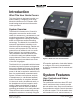
Introduction What This User Guide Covers This User Guide is designed to assist you when installing, configuring, and using Model 214 Announcer’s Consoles. Additional background technical information is also provided. System Overview The Model 214 Announcer’s Console is designed to serve as the audio control center for announcers, commentators, and production personnel. This tabletop unit supports applications utilizing the Dante® audio-over-Ethernet media networking technology.
other primary uses. Two LEDs display the on/off status of the main output. A second pushbutton switch controls the status of the talkback output channel. This is the audio signal used to communicate with producers, directors, spotters, or other behind-the-scenes production personnel. A status LED is associated with the talkback pushbutton. The pushbutton switches use gold-plated contacts for reliable longterm operation and include backlighting using white LEDs.
A large part of the Model 214’s unique power is the ability to configure the operation of the main and talkback functions. To meet the needs of the many specific broadcast and production applications, a variety of pushbutton operating modes are available. The main pushbutton can be selected to operate from among four modes. In the “push-to-mute” mode the pushbutton performs a momentary mute of the audio signal associated with the main output channel.
The first two modes support standard onair applications and use Dante audio input channels 1 and 2. In the broadcast world these two signals are often referred to as talent cue or IFB audio. In live television applications they typically originate in production trailers or control rooms and provide one channel of program-withinterrupt audio and a second channel with program-only audio. The third and fourth configuration modes allow all four of the Dante-provided audio sources to be utilized.
used for sidetone it will always allow the sidetone signal to be fully muted. The headphone output was designed to meet the needs of contemporary headphones and headsets. Specifically, the output circuits act as voltage drivers rather than power drivers. In this configuration they can provide high output levels with very low distortion and noise, along with minimal current consumption. The output circuits can safely drive stereo or mono loads.
network connection, PoE power source, and Dante interface. Configuration and Flexibility Model 214 configuration settings can be made using twelve DIP switches and two pushbutton switches. The STcontroller software application can be used to view and change the gain of the microphone preamplifier, the on/off status of P48 phantom power, and the headphone output gain range.
200-Series should be reviewed. Complete information is available on the Studio Technologies website. Installation In this section signal interconnections will be made using the connectors located on the back panel of the Model 214. A microphone signal will be interfaced by way of a 3-pin XLR connector. A ¼-inch 3-conductor phone jack is provided for the headphone output. An Ethernet data connection will be made using either a standard RJ45 patch cable or an etherCON protected RJ45 plug.
premium-quality headsets, their total cost of ownership would have been much less. Enough said… Headphone Output The Model 214’s headphone output is compatible with stereo or mono headphones, headsets, or earpieces. Connecting devices with a nominal impedance of 100 ohms or greater is preferred. This shouldn’t prove to be an issue since essentially all of the contemporary devices meet this recommendation.
214’s power source. Alternately, an external 12 volt DC source can be connected. For redundancy, both PoE and the external source can be connected at the same time. If both PoE and an external 12 volt DC source are connected, power will be drawn only from the PoE supply. If the PoE source becomes inoperative the 12 volt DC source will provide the Model 214’s power with no interruption in operation. Pushbutton Labeling The two pushbutton switches used in the Model 214 were selected for several reasons.
To prevent unauthorized personnel from changing the configuration settings, a security panel is attached to the bottom of the Model 214’s enclosure. For convenience, the security panel provides a summary of the configurable parameters and related information. Refer to Appendix A for a representative view. The security panel is held in place by means of four rubber bumpers (“feet”) that have built-in screws. Using your fingers, remove the four bumpers so that the panel can be removed.
Selecting the correct amount of gain for an application might take a little experimentation. The goal is to bring the mic’s signal up to the Dante reference level which is typically considered to be –20 dBFS. (This is 20 dB below digital maximum.) Operating at this signal level will help ensure the delivery of “clean” audio to the destination device or devices. There’s no “perfect” gain setting that this guide can recommend.
headphone output gain range. The application is available for download on the Studio Technologies website (www.studiotech.com). Its initial release is compatible with the Windows® operating system. Changes made using the application will be displayed in real-time on the Model 214’s 2-digit display. Changes made to the mic preamp gain, P48 on/off status, and headphone output gain range using the Model 214’s pushbutton switches will be displayed in STcontroller.
• Push to Talk: In this mode the audio signal on the main output channel is normally muted. The main audio signal will become active whenever the pushbutton is pressed and held. • Latching: In this mode the audio signal on the main output channel will change between its active and muted states whenever the pushbutton is pressed. Upon power up the audio signal on the main output will be in its muted state. • Hybrid: This mode is a combination of push to talk and latching action.
Sidetone Switches SW1-5 and SW1-6 configure the way the sidetone function operates. Figure 6. Sidetone switch settings Four modes are available: • Off: In this mode the sidetone function not active. • Main Button: In this mode the sidetone function will be active whenever the audio signal is present on the main output channel. • Talkback Button: In this mode the sidetone function will be active whenever the audio signal is present on the talkback output channel.
rotary level control C1, located on the left side of the front panel. The balance (relative level) of both these signals is controlled by rotary level control C2, located in the center of the front panel. Sidetone audio is assigned to both the left and right headphone output channels and its level is controlled by rotary level control C3, located on the right side of the front panel. Audio inputs 3 and 4 are not used.
When the rotary level control on the right side of the front panel has been assigned to control the sidetone level the setting of the headphone minimum level mode will not impact it. In this case when the control is in its fully counterclockwise position it will always cause the sidetone level to be fully muted. System Mode Switches SW1-11 and SW1-12 are used to configure the overall operating mode of the Model 214.
attenuated) by 18 dB whenever the main or talkback output channels have audio present. In this way the two output channels can be used independently, with neither impacting the other. And, the headphone output can be connected to amplified loudspeakers. The speakers will reduce in level whenever one of the output channels is active, preventing acoustical feedback.
applications 48 kHz will be appropriate. The Model 214 can serve as the clock master for a Dante network but in most cases that would not be optimal. Operation At this point the audio, Ethernet, and power connections should have been made. The pushbutton labels may have been revised. The desired configuration should have be made using the pushbutton and DIP switches. The Dante receiver (input) and transmitter (output) channels should have been routed using the Dante Controller software application.
three rotary controls. These are simple to operate and understand, as will be described in later paragraphs. After a few seconds the LED identification patterns will cease and normal Model 214 operation will again take place. Ethernet, PoE, and Dante Status LEDs Signal Present/Peak LED Four status LEDs are located below the etherCON connector on the Model 214’s back panel. The LINK/ACT LED will light green whenever an active connection to a 100 Mb/s Ethernet network has been established.
but rather allow the pushbutton’s labeling and location to be visible in low-light conditions. Main Button and LED Indicators The pushbutton on the left, factory labeled as COUGH, functions according to the selected configuration. Two LED indicators, located directly above the pushbutton, are associated with the status of the audio signal on the main output channel. The green LED, located on the right, is lit whenever the microphone audio signal is connected to the main output channel.
Talkback Button and LED Indicator The pushbutton on the right, factory labeled TALKBACK, controls the audio signal associated with the talkback output channel. The manner in which the talkback pushbutton functions depends on the way it was configured. One LED indicator, green in color, is located directly above the talkback pushbutton. It lights whenever the microphone audio signal is connected to the talkback output channel.
channel levels can result in much happier, and more productive, users. One of the headphone output modes uses the control in the center of the unit as a balance function. In this case the detent position will send approximately equal levels to both the left and right headphone output channels. This is as one would expect from a “stereo” balance control such as provided in consumer electronic equipment.
this is more involved than letting DHCP or link-local “do their thing,” if fixed addressing is necessary then that capability is available. But in this case it’s highly recommended that each unit be physically marked, e.g., directly using a permanent marker or “console tape,” with its specific IP address. If knowledge of a Model 214’s IP address has been misplaced there is no reset button or other method to restore the unit to a default IP setting.
headset. Other uses include creating a “loop through” or “mult” function for the microphone input or headphone output connections. A number of interface cable assemblies, along with some special function kits, are available from Studio Technologies. Please refer to the website for details on what is available. The spare connector locations are compatible with the Neutrik DL-series of connectors. For flexibility, XLR versions are available that provide from three to seven contacts.
attached. These wires, approximately 12 inches in length, allow convenient soldering to a connector selected to be installed in a spare location on the Model 214’s back panel. For reference, the wire color for pin 1 is gray, pin 2 is yellow, and pin 3 is blue. The heat-shrinkable tubing is provided so that the connector terminals or “solder cups” can be insulated from each other. It will also provide some strain relief to the solder joints.
insertion of a pluggable T-1 bi-pin incandescent bulb. But they are also compatible with the more modern leaded T-1 LEDs. As of the time of writing this guide the specific LED used at the factory is the Kingbright WP7104QWC/D. If backlighting is not desired it’s easy to remove the LED lamps. The mating socket in each pushbutton assembly is accessed by carefully removing the pushbutton’s lens cap, graphic label, and frosted lens.
5. Apply power to the Model 214. Power can be provided by Power-over-Ethernet (PoE) associated with a connected Ethernet signal or can be from an external 12 volt DC source. 6. The Model 214 will run a “boot loader” program that will immediately load the new MCU (m214.bin) file. This process takes only a few seconds. During this time period the LED located below the USB connector will flash slowly on and off green.
Specifications Power Sources: Power-over-Ethernet (PoE): class 2 (low power) per IEEE 802.3af External: 10 to 18 volts DC, 270 mA max @ 12 volts DC Network Audio Technology: Type: Dante audio-over-Ethernet Bit Depth: up to 24 Sample Rates: 44.
Appendix A Attached to the bottom of the unit is a security panel with text that provides a summary of the configurable parameters and related information. Model 214 User Guide Studio Technologies, Inc.
Appendix B The following list provides details on the 3-pin header connectors located on the Model 214’s printed circuit board. Shown are both reference numbers and associated functions.