
Manual


Model 209 User Guide Issue Preliminary 1, July 2021
Studio Technologies, Inc. Page 9
MODEL 209
TALENT CONSOLE
a 1000BASE-T (GigE) connection is not supported
unless it can automatically “fall back” to 100BASE-TX
operation. The Model 209 supports Ethernet switch
power management, enumerating itself as a PoE
class 2 device.
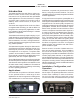
The Ethernet connection is made by way of a
standard RJ45 jack that is located on the back of
the Model 209’s enclosure. This allows connection
by way of a cable-mounted standard RJ45 plug.
The Model 209’s Ethernet interface supports auto
MDI/MDI-X so that a “cross-over” or “reversing” cable
will never be required.
Microphone Input
The Model 209 provides a 3-pin female XLR con-
nector for interfacing a microphone with the high-
performance input circuit. The connected microphone
can be a standalone handheld (“stick”) type or can
be part of a broadcast-style headset. The Model
209’s microphone input is directly compatible with
balanced dynamic, ribbon, or P48 phantom powered
microphones. A microphone should be connected
such that its common is on connector pin 1, its signal
high (+) is on connector pin 2, and its sign low (–) is
on connector pin 3.
An STcontroller configuration setting allows the P48
microphone power source to be enabled or disabled
as desired. The gain of the microphone preamplifier
can also be configured over a 20 to 65 dB range.
Details on configuring the unit will be described later
in this guide.
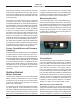
Headphone Output
The Model 209 provides a 2-channel (“stereo”)
headphone output by way of a both a 3-conductor
¼-inch phone jack and a 3.5 mm TRS jack. Both are
located on the front panel. Devices such as stereo
headphones or “dual-ear” broadcast-style headsets
can be directly connected using a 3-conductor ¼-inch
plug. Following the usual convention, the left channel
should be terminated on the tip lead, the right channel
on the ring lead, and common on the sleeve lead.
It’s also possible to use a monaural (“single-ear”)
headset or broadcast-type single earbud as long as
sufficient care is taken. If a 3-conductor ¼-inch plug
is used by the device it should be wired such that
the tip lead is connected to the positive terminal of
the transducer and the sleeve lead is connected to
the negative or common lead of the transducer; the
plug’s ring should be left unconnected. But it’s also
likely that the monaural device will be terminated on
a 2-conductor (tip and sleeve) ¼-inch plug. When
a plug of this type is inserted into the Model 209’s
headphone output connector (jack) the Model 209’s
right headphone output channel will be shorted. (This
will occur since the ring lead will be directly shorted to
the sleeve lead.) This can lead to stress on the Model
209’s right channel headphone output circuitry as
well as drawing extra current from the output stage.
To prevent this condition from occurring the Head
-
phone Output – Routing configuration choice should
be set for Single-Channel Mono. This disables the
right headphone output channel and sends the listen
audio source or sources only to the left headphone
output channel. Refer to a later section in this guide
for details on configuring the headphone output.
Remote Control Inputs
The Model 209 allows connection of two remote
control signals. Configuration settings in STcontroller
allow the remote control inputs, referred to as GPI 1
and GPI 2, to impact several Model 209 functions.
(GPI refers to “general purpose input.”) The exact
functioning of the two remote control inputs is deter-
mined by configuration settings, details of which are
discussed later in this guide.
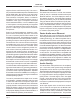
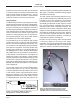
A 3-conductor (TRS) 3.5 mm jack is located on the
Model 209’s back panel and provides access to the
two remote control inputs. Each input circuit is “ac
-
tive low,” with a 3.4 k (3400) ohm resistor connected
to +3.3 volts DC to act as an input “pull up.” (In
addition, a combination of resistors and capacitors
provide ESD protection, minimizing the chance of
damage due to static discharge or other extraneous
signals.) A current flow of less than one milliampere
is required for a remote control input to be recognized
as active.
Figure 3. 3-conductor (TRS) 3.5 mm plug
configured for use with remote control inputs