
Manual


Issue Preliminary 1, July 2021 Model 209 User Guide
Page 8 Studio Technologies, Inc.
MODEL 209
TALENT CONSOLE
ated with the excellent on-air microphone mounting
products from Yellowtec® of Germany. With just two
connections the Model 209 can control both the white
and red LED indicators associated with the m!ka
mounting system.
The status of the tally outputs can be configured
to respond to six sources. “Virtual” buttons within the
STcontroller application can control the on/off status of
the tally outputs. This can be useful during unit instal-
lation and testing. The status of the main output can
also be used to control the tally outputs. This allows
a direct “on-air” light function to be established. As
previously noted, the two contact closure inputs can
be used to control the tally outputs. Finally, a high-
frequency tone present in a Dante receiver (input)
channel can also be configured to control the state of
a tally output. This tone-operated (TOX) control func-
tion allows easy integration with a DSP-based audio
processing unit. With no additional wiring and simple
programming, the processor can generate tones
required to control the state of the tally outputs.
Future Capabilities and Firmware
Updating
The Model 209 was designed so that its capabilities
and performance can be enhanced in the future.
A USB receptacle, located on the unit’s back panel,
allows the application firmware (embedded software)
to be updated using a USB flash drive. The Model
209 uses Audinate’s Ultimo™ integrated circuit to
implement the Dante interface. The firmware in this
integrated circuit can be updated via the Ethernet
connection, helping to ensure its capabilities remain
up to date.
Getting Started
What’s Included
Included in the shipping carton will be a Model 209
Talent Console and instructions on how to obtain
an electronic copy of this guide. As a device that is
Power-over-Ethernet (PoE) powered, no external
power source is provided.
In this section the unit will be mounted under a table
-
top, desk, stage set, or other flat surface. Once that
has been completed signal interconnections will be
made using the connectors located on the front and
back surfaces of the Model 209’s enclosure. Ethernet,
microphone, remote control input, and tally output
interfacing will be performed on the unit’s back panel.
Headphone connections will be made by way of either
of the two connectors on the unit’s front panel.
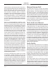
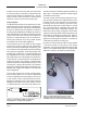
Mounting the Unit
Four screws are used to mount the Model 209’s en-
closure to the underside of a flat surface. The specific
type of fastener would depend on the surface material
that the unit is being mounted to. The overall size of
the necessary mounting hardware would meet the
standard for #6 (English) or 3 mm (metric). Refer
to Appendix B, located at the end of this guide, for
mounting-dimension details.
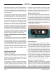
Figure 2. Model 209 Talent Console shown in an
under-tabletop mounting configuration
Connections
An Ethernet data connection with power-over-Ether-
net (PoE) capability will be made using a standard
patch cord that is terminated with an RJ45 plug. A
microphone will be connected using a cable-mounted
3-pin male XLR connector. If one or both of the re-
mote control inputs is going to be utilized, they will
be connected by way of a 3-conductor (TRS) 3.5 mm
plug. Two tally outputs are available on the back panel
and interfaced using another 3-conductor (TRS) 3.5
mm plug. On the front panel are two jacks that are
provided for use by headphones, the earpieces of
headsets, or wired ear buds. Both are 3-conductor
(stereo), one being ¼-inch and the other 3.5 mm.
Ethernet Connection with PoE
A 100BASE-TX Ethernet connection that supports
power-over-Ethernet (PoE) is required for Model 209
operation. This one connection will provide both the
Ethernet data interface and power for the Model 209’s
circuitry. A 10BASE-T connection is not sufficient and