
Manual


Issue Preliminary 1, July 2021 Model 209 User Guide
Page 10 Studio Technologies, Inc.
MODEL 209
TALENT CONSOLE
Prepare the interconnecting cable and associated
3-conductor (TRS) 3.5 mm plug to reflect that the tip
lead is used by remote control input GPI 1, the ring
lead by remote control input GPI 2, and the sleeve
lead is the common connection for both inputs.
Tally Outputs
The Model 209 provides two general-purpose “tally”
outputs that can be used for a variety of applications.
Each can directly drive an LED array or be utilized by
the input on another piece of equipment. The state of
the tally outputs (disabled or enabled) can follow the
state of Model 209’s main Dante transmitter (output)
channel, the state of the remote control inputs, the
presence of a high-frequency tone on the Dante re-
ceiver (input) channels, or by using “virtual” buttons
accessible in the STcontroller application.
The important thing to note about the tally outputs
is that they provide 12 volts DC with a significant
amount of current (100 milliamperes maximum). This
is in contrast to more-typical tally outputs provided by
other pieces of equipment. These tally outputs may
provide “logic” signals of 3.3 or 5 volts DC with just a
few milliamperes of current. While the Model 209’s
tally outputs are much more flexible, it’s important to
ensure that the connected devices can support the
voltage and current. For example, a series resistor
might be required if a Model 209 tally output is to be
connected to a single LED indicator. Two resistors
that create a voltage divider might be needed for com
-
patibility with an input that requires a more-standard
logic voltage level.
The two tally outputs can function independently,
each providing either 0 or 12 volts DC, depending
on their configuration and output status. (The source
or sink current of each output is limited to 100 mil
-
liamperes.) Settings in the STcontroller software
application also allow the two tally outputs to serve
in a differential mode. In this way, tally output 2 can
provide an output that is always opposite in polarity to
tally output 1, something required to directly support
bi-directional LED arrays.
The tally outputs were expressly designed to sup
-
port the status indicator LED assembly that can be
included as part of the m!ka-series of microphone
mounting arms from Yellowtec (yellowtec.com).
Specifically provided are the tally output’s 12 volts
DC, 100 mA maximum capability along with two
differential output mode configuration settings. The
Model 209 can be easily configured to allow direct
support for m!ka’s bi-directional LED assembly. This
will enable the assembly’s two LED colors, depend-
ing on the status of Model 209 resources. Refer to
Appendix C of this guide for details on connecting to
a Yellowtec microphone mounting arm.
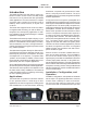
Prepare an interconnecting cable and associated
3-conductor (TRS) 3.5 mm plug for the design
application. The plug’s tip lead provide access to tally
output 1, the ring lead to tally output 2, and the sleeve
lead to the common connection for both outputs.
Figure 4. 3-conductor (TRS) 3.5 mm plug
configured for use with tally outputs
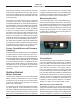
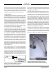
Figure 5. Model 209 Talent Console can be
configured to allow direct support for the
Yellowtec m!ka’s bi-directional LED assembly