
Manual

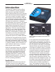
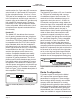
Table Of Contents

Model 207 User Guide Issue 2, June 2019
Studio Technologies, Inc. Page 9
MODEL 207
eSPORTS CONSOLE
The Ethernet connection is made by way
of a Neutrik etherCON protected RJ45
connector that is located on the back of the
Model 207’s enclosure. This allows connec-
tion by way of a cable-mounted etherCON
connector or a standard RJ45 plug. The
Model 207’s Ethernet interface supports
auto MDI/MDI-X so that a crossover cable
is not required.
Headset Connections
The Model 207 allows two different types of
headsets to be connected. A 5-pin female
XLR connector, located on the Model 207’s
back panel, allows connection of a standard
broadcast- or intercom-style communica-
tions headset. A 3.5 mm 4-conductor TRRS
jack, also located on the back panel, allows
a computer gaming headset to be directly
connected. The Model 207’s two headset
connectors are electrically wired in parallel.
As such, only one type of headset should
be connected at one time.
Headset A
The Model 207 provides a 5-pin female
XLR connector that interfaces with the
microphone and headphone connections
of a single- or dual-ear intercom or broad-
cast-style headset. The connector is labeled
Headset A. Refer to Figure 2 for connection
details. The microphone input connections
are compatible with most unbalanced dy-
namic or electret (low-voltage DC-powered)
microphones. A balanced dynamic micro-
phone should, in most cases, also function
correctly if its signal – (low) is connected to
Model 207’s mic in –/shield connection. No
support is provided for microphones that
require P12 or P48 phantom power.
To allow users of stereo (dual-earpiece or
“double-muff”) headsets to hear a monaural
version of the two headphone output chan-
nels does not require special wiring of the
5-pin male XLR mating connector. The head-
set’s left headphone channel should always
be wired to pin 4 and the right headphone
channel to pin 5. Configuration choices,
discussed later in this guide, can then be
used to create the desired monaural output.
It’s important not to connect together (short)
pins 4 and 5 of the headset’s connector as
damage to the Model 207’s output circuitry
could result.
A monaural (single-earpiece or “single-muff”)
headset should be wired such that its head-
phone is wired only to pin 4; pin 5 should
be remain unused. Configuration choices,
discussed later in this guide, can be used
to create a monaural output.
It’s possible that some Beyerdynamic head-
set interconnecting cable assemblies termi-
nate the earpiece’s left and right connections
opposite from what the Model 207 and other
broadcast equipment require. These cables
may terminate the left earpiece to pin 5 of
the 5-pin male XLR connector and the right
earpiece to pin 4. If this condition is present
it will require reversing or “flipping” the two
wires in a headset’s connector such that the
left earpiece connects to pin 4 and the right
earpiece to pin 5.
If a separate microphone and pair of head-
phones need to be connected an adapter
cable assembly should be fabricated. It
Figure 2. Headset A connection pinout chart