
Manual

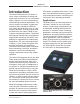
Table Of Contents

Issue 2, October 2018 Model 204 User Guide
Page 10 Studio Technologies, Inc.
MODEL 204
ANNOUNCER’S CONSOLE
Three system modes select the overall
way in which the Model 204 functions. The
on-air mode is optimized for applications
where users will be on-air talent that must
maintain strict separation between on-air
and production audio channels. Other
applications will benefit from the two avail-
able production modes.
Future Capabilities and
Firmware Updating
The Model 204 was designed so that
its capabilities and performance can be
enhanced in the future. A USB connector,
located on the unit’s main circuit board
(underneath the unit’s cover), allows the
application firmware (embedded software)
to be updated using a USB flash drive.
The Model 204 uses the Audinate Ultimo™
integrated circuit to implement the Dante
interface. The firmware in this integrated
circuit can be updated via the Ethernet
connection, helping to ensure that its
capabilities remain up to date.
Getting Started
What’s Included
Included in the shipping carton are a
Model 204 Announcer’s Console and a
printed copy of this guide. As a device that
is Power-over-Ethernet (PoE) powered, no
external power source is provided. In most
applications an Ethernet switch with PoE
capability will be utilized. If that’s not avail-
able a PoE midspan power injector can be
used.
Connections
In this section signal interconnections will
be made using the five connectors located
on the back of the Model 204’s enclosure.
An Ethernet data connection with Power-
over-Ethernet (PoE) capability will be
made using either a standard RJ45 patch
cable or an etherCON protected RJ45
plug. A microphone will be connected us-
ing a cable-mounted 3-pin male XLR con-
nector. A set of headphones or an earpiece
will be connected by way of a ¼-inch plug.
If desired, the Model 204’s microphone-
level output may be interfaced with other
equipment using a cable terminated with
a standard 3-pin female XLR connector.
Special applications may utilize the two
remote control inputs that are accessible
using a 3.5 mm 3-conductor jack.
Ethernet Connection with PoE
A 100BASE-TX Ethernet connection that
supports Power-over-Ethernet (PoE) is
required for Model 204 operation. This one
connection will provide both the Ethernet
data interface and power for the Model
204’s circuitry. A 10BASE-T connection is
not sufficient and a 1000BASE-T (“GigE”)
connection is not supported unless it can
automatically “fall back” to 100BASE-TX
operation. The Model 204 supports Ether-
net switch power management, enumerat-
ing itself as a PoE class 2 device.
The Ethernet connection is made by way
of a Neutrik etherCON protected RJ45
connector that is located on the back of
the Model 204’s enclosure. This allows
connection by way of a cable-mounted
etherCON connector or a standard RJ45
plug. The Model 204’s Ethernet interface
supports auto MDI/MDI-X so that a “cross-
over” or “reversing” cable will never be
required.
Ethernet Connection without PoE
As previously discussed in this guide, the
Model 204 was designed such that the
Ethernet connection will provide both data