Model 204 Announcer’s Console User Guide Issue 2, October 2018 This User Guide is applicable for serial numbers M204-00151 and later with application firmware 1.2 and later Copyright © 2018 by Studio Technologies, Inc., all rights reserved www.studio-tech.
This page intentionally left blank.
MODEL 204 ANNOUNCER’S CONSOLE Table of Contents Revision History ........................................................... 4 Introduction ................................................................... 5 Getting Started ............................................................. 10 Operation ...................................................................... 19 Technical Notes ............................................................ 24 Specifications ..........................................
MODEL 204 ANNOUNCER’S CONSOLE Revision History Issue 2, October 2018: • Documents addition of the Push to Mute/Tap to Latch main button operating mode. Issue 1, May 2018: • Initial release. Issue 2, October 2018 Page 4 Model 204 User Guide Studio Technologies, Inc.
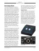
MODEL 204 ANNOUNCER’S CONSOLE Introduction The Model 204 Announcer’s Console offers a unique combination of analog and digital audio resources for use in broadcast sports, eSports, live event, entertainment, and streaming broadcast applications. The unit is housed in a compact, rugged steel enclosure that’s intended for table-top use. Calling the Model 204 “cute” or “cool” would be accurate; its nicely proportioned but diminutive size makes it ideal for use in space-constrained locations.
MODEL 204 ANNOUNCER’S CONSOLE function can provide the user with a microphone confidence signal. Two Dante audio output channels, one designated as main and the other as talkback, are routed via an associated local-area network (LAN) to inputs on Dante-compatible devices. Two pushbutton switches, main and talkback, provide the user with direct control over audio routing. The audio switching is performed in the digital domain and is virtually “click-free.
MODEL 204 ANNOUNCER’S CONSOLE of Model 204 operating parameters. This allows the unit’s performance to be optimized to meet the needs of specific applications. The user is presented with two pushbutton switches and three push-in/push-out rotary level potentiometers. This makes it easy to control the status of the main and talkback outputs as well as adjusting the signals that are sent to the headphone channels.
MODEL 204 ANNOUNCER’S CONSOLE This provides flexibility, allows precise control, and keeps the three level potentiometers from having to directly handle analog audio signals. The audio channels destined for the phones outputs are sent to a high-performance digital-to-analog converter and then on to robust driver circuitry. High signal levels can be provided to a variety of headsets, headphones, and earpieces.
MODEL 204 ANNOUNCER’S CONSOLE interrupt to enter the Model 204 by way of Dante input (receiver) channel 1 and be sent to the left headphone output. Program-only audio, entering the unit by way of Dante input channel 2, would be sent to the right headphone output. Pots A and B are used to adjust the level of those signals. Pot C is used for the sidetone function where microphone audio is sent to both the left and right channels of the headphone output.
MODEL 204 ANNOUNCER’S CONSOLE Three system modes select the overall way in which the Model 204 functions. The on-air mode is optimized for applications where users will be on-air talent that must maintain strict separation between on-air and production audio channels. Other applications will benefit from the two available production modes. Future Capabilities and Firmware Updating The Model 204 was designed so that its capabilities and performance can be enhanced in the future.
MODEL 204 ANNOUNCER’S CONSOLE and Power-over-Ethernet (PoE) power. There may be situations where the associated Ethernet switch does not provide PoE power. In such cases an external PoE midspan power injector can be used. If the selected midspan power injector is 802.3afcompatible it should function correctly. Midspan units are available from a variety of sources, including many online retailers.
MODEL 204 ANNOUNCER’S CONSOLE the output is identical to the signal that’s connected to the microphone input but with a solid-state muting circuit in series with the interconnection. When the Model 204’s Dante main output channel is active the microphone signal will also pass through to the Model 204’s microphone output connector. Whenever the Dante main output channel is muted the microphone signal does not pass through to the microphone output connector; it is muted in an essentially click-free manner.
MODEL 204 ANNOUNCER’S CONSOLE The Model 204 uses the Ultimo 4-input/ 4-output integrated circuit to implement the Dante functionality. The Model 204 can also be configured to meet the requirements of the AES67 standard. This requires a setting to be enabled within the Device Info section of the Dante Controller application. The two Dante transmitter (Tx) channels associated with the Model 204’s Dante interface must be assigned to the desired receiver channels on associated equipment.
MODEL 204 ANNOUNCER’S CONSOLE • Main and talkback button operating modes • System operating mode • Remote control inputs • Button backlight intensity Changes made using STcontroller will be immediately reflected in the unit’s operation; no Model 204 “reboot” is required. Each time a change is made the main and talkback buttons on the front panel will momentarily flash orange in a distinctive pattern to indicate that a command from STcontroller has been received.
MODEL 204 ANNOUNCER’S CONSOLE Mode 1 – Ch1L/Ch2R/SidetoneLR Mode 1 is provided for on-air applications where two independent audio sources need to be routed separately to the two headphone output channels. Dante input (receiver) channel 1 will be routed to the left headphone output channel and pot A will adjust its level. Dante input (receiver) channel 2 will be routed to the right headphone output channel and pot B will adjust its level.
MODEL 204 ANNOUNCER’S CONSOLE Headphone Gain Range The overall level of the headphone output can be configured as desired for specific applications. The default setting, low, is designed so that users with typical audio input sources will be inclined to set the rotary potentiometers at approximately 50% of rotation. This would be appropriate for most applications.
MODEL 204 ANNOUNCER’S CONSOLE • Talkback Button: In this mode the sidetone function will be active whenever the talkback function is active and the audio signal is present on the talkback Dante output channel. • Main and Talkback Buttons: In this mode the sidetone function will be active whenever the audio signal associated with the mic input is present on the Dante main output channel and the microphone output connector. The sidetone function will also be active whenever the talkback function is active.
MODEL 204 ANNOUNCER’S CONSOLE Button Operation – Talkback The manner in which the talkback button functions can be configured. There are three mode choices available: • Push to Talk: If this mode is selected the talkback function will normally be inactive and the LED associated with the talkback button will not be lit. Whenever the talkback button is pressed the talkback function will become active and its green LED will light.
MODEL 204 ANNOUNCER’S CONSOLE acoustical feedback will occur in applications where the headphone output is connected to the inputs on amplified speakers (or inputs on an amplifier associated with loudspeakers). In this mode the level of the headphone output channels is reduced by 18 dB whenever a main or talkback function is active. This mode is not appropriate when headphones are going to be connected to the Model 204! Remote Control Inputs There are two remote control inputs.
MODEL 204 ANNOUNCER’S CONSOLE that sequence has completed and the Dante connection has been established full operation will begin. The various LEDs will then become operational, displaying the status of their designated functions. How to Identify a Specific Model 204 Functions within the Dante Controller and STcontroller software applications allow a specific Model 204 unit to be identified. Each application provides an “eyeball” icon that when clicked will activate the Identify function.
MODEL 204 ANNOUNCER’S CONSOLE COMP LED lights solid while a user is talking at a normal voice level this will typically indicate that the microphone preamplifier gain setting should be reduced. Conversely, if the COMP LED almost never lights when normal talking is taking place, it’s possible that changing the gain to a higher value would be beneficial. Note that due to the design of the circuitry the compressor active LED will function whether or not the main or talkback functions are active.
MODEL 204 ANNOUNCER’S CONSOLE • Push to Mute/Tap to Latch: This mode is a combination of the Push to Mute and Latching modes. Whenever the main button is momentarily “tapped” its status will alternate between active and muted. When the main button’s function is active and the main button is pressed and held the audio signal will mute on both the Dante main output channel and the microphone output connector. It will stay in this condition until the main button is released.
MODEL 204 ANNOUNCER’S CONSOLE • On-Air: When the system operating mode has been selected to on-air the main button will be forced to be inactive whenever the talkback function is active. The on-air mode will be appropriate for all on-air broadcast applications where it’s imperative that the audio signal on the Dante main output channel and microphone output connector be muted whenever on-air talent uses the talkback function to communicate with production personnel.
MODEL 204 ANNOUNCER’S CONSOLE Technical Notes IP Address Assignment By default the Model 204’s Ethernet interface will attempt to automatically obtain an IP address and associated settings using DHCP (Dynamic Host Configuration Protocol). If a DHCP server is not detected an IP address will automatically be assigned using the link-local protocol. This protocol is known in the Microsoft® world as Automatic Private IP Addressing (APIPA). It is also sometimes referred to as auto-IP (PIPPA).
MODEL 204 ANNOUNCER’S CONSOLE Application Firmware Version Display There are two ways in which the version number of the Model 204’s application firmware (embedded software) can be identified. One requires only the Model 204 unit and involves a button-press sequence performed upon power up. The other method utilizes the Model 204 and the STcontroller software application. Either method may prove to be useful when working with factory personnel on application support and troubleshooting.
MODEL 204 ANNOUNCER’S CONSOLE Once the USB flash drive is inserted into the USB interface, located on the main circuit board under the cover, the unit must be powered off and again powered on. At this point the file will automatically load. The precise steps required will be highlighted in the next paragraphs of this guide. To install an application firmware file follow these steps: 1. Disconnect power from the Model 204. This will entail removing the Ethernet connection that is providing PoE power. 2.
MODEL 204 ANNOUNCER’S CONSOLE using the 4-input/4-output Ultimo integrated circuit from Audinate. The Dante Controller software application can be used to determine the version of the firmware (embedded software) that resides in the Ultimo “chip.” The STcontroller software application can also be used to identify the firmware version. (Use the Version selection under the Device tab.) The Dante firmware can be updated by way of the Model 204’s Ethernet connection.
MODEL 204 ANNOUNCER’S CONSOLE Specifications Power Source: Power-over-Ethernet (PoE): class 2 (low power, ≤6.49 watts) Network Audio Technology: Type: Dante audio-over-Ethernet AES67-2013 Support: yes Dante Domain Manager (DDM) Support: yes Bit Depth: up to 24 Sample Rate: 44.
MODEL 204 ANNOUNCER’S CONSOLE Appendix A: Model 204 Block Diagram The following block diagram shows a simplified version of the Model 204’s microphone input and microphone output circuitry. Model 204 User Guide Studio Technologies, Inc.