Model 374A Intercom Beltpack User Guide Issue 4, February 2021 This User Guide is applicable for serial numbers M374A-02501 to 04000 with application firmware 2.1 and later Copyright © 2021 by Studio Technologies, Inc., all rights reserved studio-tech.
This page intentionally left blank.
MODEL 374A INTERCOM BELTPACK Table of Contents Revision History ............................................................ 4 Introduction ................................................................... 5 Getting Started .............................................................. 8 Operation ...................................................................... 13 Technical Notes ............................................................. 18 Specifications .........................................
MODEL 374A INTERCOM BELTPACK Revision History Issue 4, February 2021: 1. Documents expansion of Call Indication function. Issue 3, August 2019: 1. Documents revision to STcontroller (version 2.02.00 and later) which separates microphone power and microphone gain configuration. Issue 2, April 2019: 1. Documents new receive and send call function. Issue 1, June 2018: 1. Initial release. Issue 4, February 2021 Page 4 Model 374A User Guide Studio Technologies, Inc.
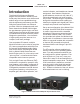
MODEL 374A INTERCOM BELTPACK Introduction The Model 374A Intercom Beltpack begins with the features offered by traditional party-line intercom user devices and adds a range of new capabilities along with the advanced performance and flexibility that Dante® audio-over-Ethernet provides. With four independent talk and listen channels the Model 374A bridges the gap between typical single- and dualchannel party-line devices and permanently installed multi-channel intercom panels.
MODEL 374A INTERCOM BELTPACK The audio quality of the Model 374A’s four audio channels is excellent, with low distortion, low noise, and high headroom. Careful circuit design and rugged components ensure long, reliable operation. A wide range of applications can be supported, including sports and entertainment TV and radio events, streaming broadcasts, corporate and government AV installations, and post-production facilities.
MODEL 374A INTERCOM BELTPACK useful to indicate to users that they are needed “on headset” or should be actively listening to an intercom channel. The call function can also be used to provide realtime cues to production personnel during the running of live events. Call signals present on the four audio input (Dante receiver) channels can be detected and displayed.
MODEL 374A INTERCOM BELTPACK Future Capabilities and Firmware Updating The Model 374A was designed such that its capabilities and performance can be enhanced in the future. A USB connector, located on the unit’s main circuit board (underneath the unit’s cover), allows the application firmware (embedded software) to be updated using a USB flash drive. The Model 374A uses Audinate’s Ultimo™ integrated circuit to implement the Dante interface.
MODEL 374A INTERCOM BELTPACK the right earpiece to pin 4. If this condition is present it will require reversing or “flipping” the two wires in a headset’s 5-pin male XLR connector such that the left earpiece connects to pin 4 and the right earpiece to pin 5. Dante Configuration Figure 2. Headset connection pinout chart connection. No support is provided for microphones that require P12 or P48 phantom power.
MODEL 374A INTERCOM BELTPACK The four Dante receiver (Rx) channels associated with the Model 374A’s audio inputs also need to be routed to the desired Dante transmitter (Tx) channels. These four audio signals can be sent to the Model 374A’s 2-channel headphone output. The Model 374A supports an audio sample rate of 48 kHz with no pull-up/pulldown values available. The Model 374A can serve as the Leader clock for a Dante network but in most cases it will be configured to “sync” to another device.
MODEL 374A INTERCOM BELTPACK Microphone Input – Electret Power Choices are Enabled or Disabled. If the headset has an electret microphone that requires a source of low-voltage DC power for operation enable the Electret Power check box. If the associated headset has a dynamic (non-powered) microphone do not enable the Electret Power check box. Most broadcast headsets that terminate on a 5-pin male XLR connector will not require microphone power.
MODEL 374A INTERCOM BELTPACK the left only, right only, or both left and right headphone channels. When using a stereo headset sending all inputs to both channels is often referred to as a dual-channel mono output. If a monaural (“single muff”) headset is used the Left configuration option allows the four input channels to be combined to monaural so that the listener can simultaneously hear both sources. Sidetone – Level Choices are Off, Low, Medium Low, Medium, Medium High, and High.
MODEL 374A INTERCOM BELTPACK When button 4 has been selected to the Call mode it will serve as a call enable button for talk channels 1, 2, and 3; microphone audio will never be sent out Dante transmitter channel 4. In the Call mode button 4 will operate in a push-to-activate manner and whenever it is active and channels 1, 2, and/or 3 are active a 20 kHz tone (call signal) will be added to the active audio paths. It will not display a call signal that’s present on audio input channel 4.
MODEL 374A INTERCOM BELTPACK Model 374A’s Dante configuration settings should have been selected using the Dante Controller software application. In this way the unit’s four audio output channels (Dante transmitter channels) and four audio input channels (Dante receiver channels) should have been routed, by way of Dante “subscriptions,” to the receiver and transmitter channels on associated Danteenabled equipment.
MODEL 374A INTERCOM BELTPACK Headphone Output Four rotary potentiometers (“pots”), located on the Model 374A’s top panel, allow individual adjustment of the level of the four audio input signals as they are sent to the 2-channel headphone output. Depending on the configuration of the unit, each audio input can be sent to the left channel, the right channel, or both the left and right channels of the headphone output.
MODEL 374A INTERCOM BELTPACK function. The button’s orange LED will light whenever audio is being sent to the headphone output. The headphone output level will continue to follow the setting of the associated rotary level control. Call (Button 4 Only) When button 4 is configured for the Call mode it will allow call signals to be generated whenever talk channels 1, 2, and/or 3 are active. The button functions in a pushto-call manner and will light orange whenever it is pressed and held.
MODEL 374A INTERCOM BELTPACK presence of a call signal. Also, if channel 4 has been configured to the Call mode that channel will not respond to a call signal on audio input 4. The Model 374A will not confuse a normal talk audio signal with a call signal. Digital filters within the unit’s processor integrated circuit limits each channel’s high-frequency response, helping to ensure that false call detection won’t take place.
MODEL 374A INTERCOM BELTPACK (from among channels 1, 2, and 3) will add 20 kHz to their audio output channels and have their associated LED flash, alternating between green and orange. (Green indicates that the talk function is active and orange indicates that the call function is active.) Release button 4 and the sending of call signals will cease. As expected, pressing button 4 when no talk channels are active will result in no call tones being generated.
MODEL 374A INTERCOM BELTPACK is active on the LAN. Even two Danteenabled devices that are directly interconnected using an RJ45 patch cable will, in most cases, correctly acquire IP addresses and be able to communicate with each other. An exception does arise when trying to directly interconnect two Dante-enabled devices that use Ultimo integrated circuits to implement Dante.
MODEL 374A INTERCOM BELTPACK 374A unit and involves a button-press sequence performed upon power up. The other method utilizes the Model 374A and the STcontroller software application. Either method may prove to be useful when working with factory personnel on application support and troubleshooting. will provide lots of useful information. This includes the application firmware version and well as details on the firmware present in the Ultimo integrated circuit.
MODEL 374A INTERCOM BELTPACK Once the USB flash drive is inserted into the USB interface, located on the main circuit board under the cover, the unit must be powered off and again powered on. At this point the file will automatically load into the processor’s flash memory. The precise steps required will be highlighted in the next paragraphs of this guide. To install the application firmware file follow these steps: 1. Disconnect power from the Model 374A.
MODEL 374A INTERCOM BELTPACK (embedded software) that resides in the Ultimo “chip.” The STcontroller software application can also be used to identify the Ultimo’s firmware version. (Use the Version selection under the Device tab.) The Ultimo firmware can be updated by way of the Model 374A’s Ethernet connection. The latest Ultimo firmware file is available on the Studio Technologies’ website. The Dante Firmware Update Manager (FUM) application program can be used to install the Ultimo firmware.
MODEL 374A INTERCOM BELTPACK Restoring Factory Defaults A command in the STcontroller software application allows the Model 374A’s configuration to be reset to the factory default values. From STcontroller select the Model 374A for which you want to restore its defaults. Select the Device tab and then select the Factory Defaults feature. Then click on the OK box. Refer to Appendix A for a list of the Model 374A’s factory default values. Model 374A User Guide Studio Technologies, Inc.
MODEL 374A INTERCOM BELTPACK Specifications Power Source: Power-over-Ethernet (PoE): class 1 (very low power, ≤3.84 watts) per IEEE® 802.
MODEL 374A INTERCOM BELTPACK Appendix A STcontroller default Model 374A configuration values: Microphone Input – Electret Power: Off Microphone Input – Gain: 42 dB Headphone Output – Channel 1 Input Routes to: Left Headphone Output – Channel 2 Input Routes to: Right Headphone Output – Channel 3 Input Routes to: Left Headphone Output – Channel 4 Input Routes to: Right Sidetone – Level: Medium Button Operation – Channels 1 through 4: Push to Talk/Tap to Latch System – Mic Kill: Global Kill Command System – C