
Model IFB Plus Series Talent Amplifier User Guide

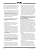
Table Of Contents

Model 2A User Guide Issue 2, March 2015
Studio Technologies, Inc. Page 21
to access the four IFB channels. Power is
provided by the Model 2A units; an external
power source is not required. A 5-position
screw terminal strip allows connection of
an optional Studio Technologies’ Model
11A Gooseneck Microphone or a line-level
signal.
The Model 24 can be mounted using
either the Model 27A 19-Inch Rack Adapter
or a custom panel cutout. The Model 27A
19-Inch Rack Adapter allows convenient
installation of a Model 24 and a Model 11A
Gooseneck Microphone into one space
of a standard rack enclosure. Refer to
the mechanical drawing in Appendix A for
details. Plenty of room remains on the right
side of the rack adapter panel, allowing
the addition of custom switches, lights, or
connectors as the specic installation may
require.
A custom Model 24 installation is dened
as any installation where you devise the
mounting method! Refer to Appendix A for
a mechanical drawing showing the dimen-
sions of the Model 24. This will assist you
in implementing your own mounting
method.
The Model 24 contains two 9-pin D-submin-
iature connectors (DE-9F). One is designat-
ed to connect to the Model 2A that provides
IFB channels 1 and 2 (unit # 1). The other
connects to the Model 2A designated for
IFB channels 3 and 4 (unit # 2). Contained
on the Model 2A is a 9-pin D-subminiature
female connector (DE-9F) that is used to
connect to the access stations. A “straight
through” cabling scheme links the Model 24
units to the Model 2A units, with pin 1 con-
nected to pin 1, pin 2 to pin 2, etc. Shielded
cable is required as the audio buses linking
a Model 24 to the Model 2As are unbal-
anced. The shield should be connected to
pin 1 on the DE-9M connectors. For refer-
ence, the chart shown in Figure 9 displays
the signals associated with the access
station connector.
Pin # Function
1 Common/Shield
2 Interrupt Audio (–10 dBu nomimal)
Ch 1 (Model 2A # 1) or Ch 3 (Model 2A # 2)
3 Interrupt Audio (–10 dBu nomimal)
Ch 2 (Model 2A # 1) or Ch 4 (Model 2A # 2)
4 18 volts DC (200 mA max nominal)
(Model 2A # 1 and Model 2A # 2)
5 Interrupt Control (pulled up to +5 V)
Ch 1 (Model 2A # 1) or Ch 3 (Model 2A # 2)
6 Interrupt Control (pulled up to +5 V)
Ch 2 (Model 2A # 1) or Ch 4 (Model 2A # 2)
7 Lamp Voltage (9.6 V dim, 14.5 V bright)
Ch 1 (Model 2A # 1) or Ch 3 (Model 2A # 2)
8 Lamp Voltage (9.6 V dim, 14.5 V bright)
Ch 2 (Model 2A # 1) or Ch 4 (Model 2A # 2)
9 Monitor Out Mute Control (pulled up to +5 V)
(Model 2A # 1 and Model 2A # 2)
Note:
Connector type on Model 2A is a 9-pin D-subminia-
ture female (DE-9F). Installer must provide a 9-pin
D-subminiature male (DE-9M). Connector uses 4-
40 threaded inserts for locking with mating plug.
Figure 9. Model 24 Access Station Connections
For best performance, a maximum total
cable length of 500 feet should be used to
link Model 24s to the Model 2As. Minimiz-
ing the cable length reduces the total ex-
posure the unbalanced audio buses have
to noise pickup, etc. Cable runs longer
than 500 feet are possible but should be
carefully checked for correct operation.
If more than one Model 24 is going to
be installed some method of “multing”
or “splitting” the 9-pin D-subminiature