
Model IFB Plus Series Talent Amplifier User Guide
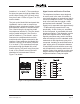
Table Of Contents

Issue 2, March 2015 Model 2A User Guide
Page 18 Studio Technologies, Inc.
Model 22 Access Stations
The Model 2A allows the connection of up
to four Model 22 Access Stations. The Mod-
el 22 provides an unbalanced microphone
input, a balanced line-level input, two light-
ed pushbutton switches, and related circuit-
ry. Power is provided by the Model 2A so
an external power source is not required. A
cable with 9-pin D-subminiature male (DE-
9M) connectors on each end links a Model
2A Central Controller with the rst Model 22
Access Station. Identical cables are used to
interconnect up to three additional Model 22
units in a daisy-chain fashion. A 5-position
screw terminal strip, located on the rear of
the Model 22, allows connection of either a
Studio Technologies’ Model 11A Gooseneck
Microphone or a line-level audio signal.
Mounting Methods
There are three mounting methods ap-
propriate for the Model 22: the Model 25A
19-Inch Rack Adapter, the Model 28A Panel
Adapter, or a custom implementation. The
Model 25A 19-Inch Rack Adapter allows a
Model 22 and a Model 11A Gooseneck
Microphone to be mounted in a single
space (1U) of a standard 19-inch rack.
Refer to Appendix A for details on how the
Model 22 is physically positioned in the
Model 25A 19-inch Rack Adapter. Plenty
of room remains on the right side of the
rack adapter plate, allowing the addition of
custom switches, lights, or jacks as your
installation may require. (Of course any
modications will have to be implemented
by installation personnel.)
The Model 28A Panel Adapter allows the
installation of a Model 22 and a Model 11A
Gooseneck Microphone in a “cut out” made
in a desk, console, or other enclosure.
Refer to Appendix A for a mechanical
drawing of the panel adapter and the re-
quired dimensions of the mounting opening.
A custom Model 22 installation is any ap-
plication where installation personnel devise
an alternative mounting method. Refer to
Appendix A for a mechanical drawing show-
ing detailed dimensions of the Model 22.
Interconnect Wiring
Contained on both the Model 2A and the
Model 22 are 9-pin D-subminiature female
(DE-9F) connectors. A “straight through”
cabling scheme links the units together, with
pin 1 connected to pin 1, pin 2 to pin 2, etc.
Shielded cable is required as the two audio
buses linking the Model 22 units to a Model
2A are unbalanced. The shield should be
connected to pin 1 on the 9-pin plugs. For
reference, the following chart displays the
signals associated with the access station
connector:
Pin # Function Direction
1 Common/Shield Input/Output
2 Interrupt Audio, Ch 1 Input
3 Interrupt Audio, Ch 2 Input
4 18 volts DC Output
5 Interrupt Control, Ch 1 Input
6 Interrupt Control, Ch 2 Input
7 Lamp Voltage, Ch 1 Output
8 Lamp Voltage, Ch 2 Output
9 Monitor Output Mute Control Input
Note:
Connector type on Model 2A is a 9-pin D-subminia-
ture female (DE-9F). Installer must provide a 9-pin
D-subminiature male (DE-9M). Connector uses
4-40 threaded inserts for locking with mating plug.
Figure 8. Model 22 Access Station Connections