
Model IFB Plus Series Talent Amplifier User Guide
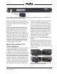
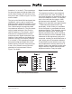
Table Of Contents

Issue 2, March 2015 Model 2A User Guide
Page 16 Studio Technologies, Inc.
• Front-panel switch allows manual
answer and hang-up (telephone line
mode)
• Front-panel operating mode and ring
activity/loop current status LEDs
• 6-position modular jack allows input and
output connections for telco interface 2
Selecting the Operating Mode
The telephone interface mode switches,
located on the back panel, are used to
select the desired operating mode—
either telephone line or standard audio. If
the telephone line mode is selected, the
Model 2A’s telephone interface connections
should, in most cases, terminate on an
I/O panel of some type. Typically this panel
might include modules jacks (“RJ11”)
and “5-way” screw binding posts. This
will allow rapid connection with telephone-
company-provided lines that arrive in a vari-
ety of wiring schemes. Because of the likely
presence of high-voltage ringing signals, it
is strongly advised to not route telephone
lines through an audio patch bay.
If the standard audio mode is selected
direct connection of an audio source is
acceptable. But connecting them via audio
patch points will provide better flexibility.
In the standard audio mode each interface
acts like a transformer-coupled balanced
audio input. Interface 1 has an input imped-
ance of 2200 ohms. Interface 2 has an in-
put impedance of 2200 ohms in the receive
mode and 700 ohms in the send mode. In
the standard audio mode, the interfaces are
compatible with balanced or unbalanced
signals. No shield connection is associ-
ated with the telephone interfaces. If pos-
sible, audio signals should be connected
to the Model 2A’s telephone interfaces, via
a modular plug and cable, using shielded
cable, with the shield wire connected to the
appropriate point at the end opposite of the
Model 2A. The shield wire should remain
unterminated at the Model 2A’s end.
Connecting to the Telephone Jacks
Modular telephone line cords are used to
connect input and output signals with the
Model 2A’s two 6-position modular jacks.
(These jacks are typically called RJ11
jacks but that’s not really technically cor-
rect. Starting in the early 1960s an RJ11
was a telephone-company-provided tele-
phone line that was terminated on pins 3
and 4 of a 6-position keyed modular jack.)
The original Model 2 and Model 2A units
just connected telco signals using pins 3
and 4. But Model 2A units with serial num-
bers 03451 and later take advantage of
the previously-unused pins and circuitry
capability. As such, the Model 2A uses
more than just pins 3 and 4 to bring signals
in to and out of the two telephone inter-
faces. This flexibility is provided to ease
installation and add enhanced functionality.
The jack on the Model 2A’s back panel that
is labeled 1 can be are used to connect
three different signals: telephone interface
1 input, telephone interface 2 input, and
telephone interface 2 switched output.
Pins 3 and 4 bring the tip and ring leads
into telephone interface 1. Pins 5 and 2
can be used to bring the tip and ring leads
into telephone interface 2. (They are elec-
trically in parallel with pins 3 and 4 of the
jack labeled 2.) This is provided so that
a single cable can carry the connections
for two lines, bringing signals into both
interface 1 and interface 2. Pins 6 and 1
can be connected to a telephone device
which would receive the signal connected
to the interface 1 input whenever the Mod-
el 2A’s interface 1 circuitry is not active