
Model IFB Plus Series Talent Amplifier User Guide
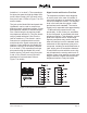
Table Of Contents

Model 2A User Guide Issue 2, March 2015
Studio Technologies, Inc. Page 15
Connecting to the Telephone
Interfaces
Caution: Never install telephone wiring
during a lightning storm. Never install
telephone jacks in wet locations unless
the jack is specifically designed for wet
locations. Never touch non-insulated
telephone wires or terminals unless the
telephone line has been disconnected
at the network interface. Use caution
when installing or modifying telephone
lines.
Overview
The Model 2A contains two telephone
interfaces which can be individually
configured to allow connection to a tele-
phone line or to a standard audio signal.
A telephone line is designated as such if
it has a DC voltage (typically –48) associ-
ated with it. This type of telephone line is
sometimes referred to as being a “wet”
line. A standard audio signal is one that is
isolated from any source of DC voltage.
Some fax adapters associated with cellular
telephones provide this type of “telephone”
line. A standard audio signal is sometimes
referred to as a “dry” signal. While this
sounds confusing, contemporary applica-
tions sometimes refer to both types of
signals as “telco.” To a large production ve-
hicle that pulls up to do a 2-week golf tour-
nament, a telco line often is one provided
by the local telephone company terminated
on an RJ11 jack. To a mobile news gath-
ering (ENG) vehicle, a telco signal might
come from an adapter associated with a
cellular telephone which in many cases is
simply a standard audio signal.
Some of the important features of the Model
2A’s telephone interfaces include:
Telephone Interface 1
• Telephone line or standard audio mode
select switch on back panel
• Used to receive audio only
• Receive audio can be used as program
and VOX source
• Front-panel ±8 dB receive level trim pot
• Front-panel switch allows manual an-
swer and hang-up (telephone line mode)
• Auto disconnect upon telco-provided
break in loop current (telephone line
mode)
• Front-panel operating mode and loop
current status LEDs
• 6-position modular jack allows input and
output connections for telco interface 1
and an input connection for telco inter-
face 2
Telephone Interface 2
• Telephone line or standard audio mode
select switch on back panel
• Used to receive or send audio
• Receive audio can be used as program
and VOX source
• Front-panel ±8 dB receive level trim pot
• Sends audio from either IFB channel
• Automatic answer of “ringing” telephone
line (telephone line mode)
• Auto disconnect upon telco-provided
break in loop current (telephone line
mode)