User Guide Issue 2, March 2015 This User Guide is applicable for serial numbers M2A-03451 and later Copyright © 2015 by Studio Technologies, Inc., all rights reserved www.studio-tech.
This page intentionally left blank.
Table of Contents Revision History ........................................................... 4 Introduction ................................................................... 5 Installation .................................................................... 12 Operation ...................................................................... 24 Configuration ................................................................ 29 Technical Notes ............................................................
Revision History Issue 2, March 2015: 1. Documented revised telco interface new capabilities and connection details: - Added the ability to connect both sources using jack 1. - Also added switched output connections. Issue 1, October 2013: 1. Initial release. Issue 2, March 2015 Page 4 Model 2A User Guide Studio Technologies, Inc.
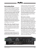
Introduction The IFB Plus Series Model 2A Central Controller from Studio Technologies is a highly integrated, 2-channel IFB (interruptible foldback) unit. It is the main component of the IFB Plus Series which is expressly designed to provide talent cueing for ENG, SNG, OB, and mobile production facilities. It can also find use in fixed installations that need a compact but feature-rich stand-alone IFB system.
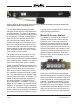
Model 24 Access Station The Model 24 Access Station allows broadcast personnel to access the four IFB channels associated with two Model 2A units. The Model 24 contains five lighted pushbutton switches, four of which are used to activate and display the status of the four IFB channels and one that provides an “all call” function. The Studio Technologies’ Model 11A Gooseneck Microphone or a line-level audio source can be connected.
50/60 hertz is connected via a detachable mains cord and provides power for the Model 2A. IFB Channels The Model 2A contains two independent IFB channels. Each channel has individual controls and indicators, including program source select switches, program level control, 5-segment LED level meter, and LED status indicators. The features of one of two identical channels will be highlighted in this paragraph.
Compressor Circuits The two IFB channels contain studio-quality compressor circuitry to control the dynamic range of the interrupt audio. These play an important role in how the Model 2A maintains high audio quality, specifically evening out level variations presented by the talk signals associated with various IFB users. The compressors make talent cues more intelligible and prevent abnormally high signal levels from reaching user’s ears. The resulting audio quality is very, very good.
mode is telephone interface 2’s auto answer function. An LED associated with each telephone interface displays when the standard audio mode is selected. Voice Operated (VOX) Interrupt The Model 2A contains circuitry to allow an audio signal to serve as both an interrupt audio source and a control signal. This eliminates the need for a separate push-to-talk button or contact closure.
Figure 3. Model 22 Access Station shown mounted in optional Model 25A 19-Inch Rack Adapter with optional Model 11A Gooseneck Microphone The two high-quality backlit pushbutton switches provide access to the Model 2A’s two IFB channels. The lights in the switches display when an interrupt is taking place on its respective channel; lighting brightly when IFB is active and dim when IFB is idle. An input select switch allows connection of a Model 11A Gooseneck Microphone or external line-level signal source.
Figure 5. Model 24 Access Station shown mounted in optional Model 27A 19-Inch Rack Adapter with optional Model 11A Gooseneck Microphone source. A second switch allows the Model 24 to mute the monitor output on each of the Model 2A units whenever an IFB channel is activated. Model 24 Access Stations connect to the associated Model 2A units using two 9-pin D-subminiature connectors. The nine conductors that link each Model 2A with the Model 24 support all the audio, signaling, and power requirements.
The Model 33A is unique in that a “mix” of IFB channels 1 and 2 can be created. Two level controls, along with a source selection switch, allows camera and production personnel to hear IFB cues from either or both channels. This allows IFB signals intended for both production personnel and on-air talent to be simultaneously monitored. Installation In this section you will be installing a Model 2A Central Controller in a standard 19-inch equipment rack.
Typically interference from outside signals will not be an issue. But precautions were taken in the Model 2A’s circuit designs to limit bandwidth, minimizing the chance that EMI and RF pickup problems will occur. The Model 2A is intended for mounting in a standard 19-inch rack, requiring one 1.75inch rack space (1U). The unit is secured to the rack’s front mounting rails using two mounting screws per side. XLR connectors that are located on the Model 2A’s back panel.
The VOX interrupt function is quite specialized and may not be used regularly in all applications. For maximum flexibility, it may be best to terminate the auxiliary audio input to a patch point in an audio patch bay. In this way, a variety of audio sources can quickly be “patched in” as the VOX interrupt input source. The VOX feature may remain unused for months or years, but when you need it there’s no substitute! The Model 2A’s VOX interrupt function performs very well, possibly better than you may think.
Connecting to the Telephone Interfaces Caution: Never install telephone wiring during a lightning storm. Never install telephone jacks in wet locations unless the jack is specifically designed for wet locations. Never touch non-insulated telephone wires or terminals unless the telephone line has been disconnected at the network interface. Use caution when installing or modifying telephone lines.
• Front-panel switch allows manual answer and hang-up (telephone line mode) • Front-panel operating mode and ring activity/loop current status LEDs • 6-position modular jack allows input and output connections for telco interface 2 Selecting the Operating Mode The telephone interface mode switches, located on the back panel, are used to select the desired operating mode— either telephone line or standard audio.
(interface 1 is “on-hook”). The connections on these pins pass through the Model 2A’s on/off control circuitry (the “off hook” relay) from pins 3 and 4. Refer to Figure 7 for connection details. The jack on the Model 2A’s back panel that is labeled 2 can be used to connect two different signals: telephone interface 2 input and telephone interface 2 switched output. Pins 3 and 4 bring the tip and ring leads into telephone interface 2.
Model 22 Access Stations The Model 2A allows the connection of up to four Model 22 Access Stations. The Model 22 provides an unbalanced microphone input, a balanced line-level input, two lighted pushbutton switches, and related circuitry. Power is provided by the Model 2A so an external power source is not required. A cable with 9-pin D-subminiature male (DE9M) connectors on each end links a Model 2A Central Controller with the first Model 22 Access Station.
For ease of installation, each Model 22 contains two 9-pin D-subminiature female connectors (DE-9F). The pins on both connectors are wired in parallel (“multed”). This allows signals to be easily “looped through” on their way to the next Model 22. For short cable runs, standard 9-pin video monitor extension cables, commonly used with older-style personal computers, are an inexpensive way to link a Model 22 with a Model 2A.
the Model 22’s terminal strip. One end of the black-colored wire is attached at the factory to the ring lead of the jack. The other end should be attached to the – terminal on the terminal strip. One end of the shield connection is attached at the factory to the sleeve of the jack. The other end should be attached to the SHLD terminal on the Model 22’s terminal strip.
to access the four IFB channels. Power is provided by the Model 2A units; an external power source is not required. A 5-position screw terminal strip allows connection of an optional Studio Technologies’ Model 11A Gooseneck Microphone or a line-level signal. pin 1 on the DE-9M connectors. For reference, the chart shown in Figure 9 displays the signals associated with the access station connector. The Model 24 can be mounted using either the Model 27A 19-Inch Rack Adapter or a custom panel cutout.
connectors will have to be provided. The simplest method is to use a short section of ribbon cable and multiple 9-pin insulations-displacement (IDC) connectors. Depending on the specific installation, the “break out” assemblies can be connected directly to the access station connectors on the Model 2A units, or can be “downstream” at one of the Model 24s. The Model 24 Access Station contains two mode switches that must be set.
The Model 24 contains a monitor mute function, which is intended to prevent acoustical feedback if the access station is located close to a monitor loudspeaker associated with the Model 2A Central Controller’s monitor output. When the monitor mute switch is set to its ON position, the monitor outputs mute whenever an interrupt occurs from that access station. Set the switch to its OFF position if muting of the monitor output is not desired.
Operation The Model 2A’s Front-Panel Controls and Indicators If you value equipment by the number of switches and lights per rack space, the Model 2A is really a standout—there is more stuff crammed onto the front panel than we thought possible! Seriously, the designers had the difficult problem of getting maximum functionality into a single rack space. They had heated arguments about the feature list, what to include, what to delete. In the end, we feel that all important features were included.
The program level control allows the program audio signal to be adjusted relative to the interrupt audio level. The interrupt level is internally fixed and serves as the reference. The gain structure was configured so that the level control set for about 70 percent of rotation (the “2-o’clock” position) will give a program level approximately equal to the interrupt level. This statement is made under the assumption that a +4 dBu program signal is selected and its associated input trim pot is correctly set.
set for the telephone line mode and DC current is flowing through the interface. The interface control switch, active only in the telephone line mode, allows the interface to be answered (taken “off hook”) or hung up (placed “on hook”). Momentarily pressing the switch to its up position, labeled ANSWER, places the interface in its active or off-hook state. If loop current is detected, the interface will stay in its off-hook state and the loop current LED will light.
small hole in the front panel, directly to the right of the routing control switch. Using an Xcelite® “greenie” straight-blade screw driver is recommended. Note that the trim pot is active only in the receive mode. Monitor Output A level control and source select switch is associated with the monitor output section. The level control adjusts the output level sent to the monitor speaker output. IFB channel 1 is monitored when the source select switch is in its up position.
pressing one of these buttons will cause the program audio source to mute, replaced with signal coming from the internal microphone. The level of the local interrupt audio signal is controlled using the compressor circuits. No user level controls are provided. Talent Amplifiers Connect an earpiece to an associated talent amplifier. (The Models 32A and 33A Talent Amplifiers provide their audio output signals on a ¼-inch 2-conductor phone jack and a 3.5 mm output jack.
Access Stations It’s important to thoroughly test all connected Model 22 and/or Model 24 Access Stations. Is the interrupt audio loud and clear? Observe the status lamps inside the pushbutton switches. Do the appropriate lamps light fully bright when an interrupt takes place? If an access station is configured to mute the Model 2A’s monitor output, ensure that the monitor speaker mutes during interrupt activity. Audio Quality In all cases, you should hear clear, clickfree audio.
other. This will allow minimal level changes when an operator switches between the four program inputs. A simple method of “calibrating” the program input trim pots is to: 1. Begin by connecting an audio level meter to the line output of IFB channel 1. The meter will connect by way of an interface cable that provides a 3-pin male XLR. Set the meter to display the audio signal level in terms of dBu, i.e., level in dB referenced to 0.775 volts RMS with no defined load impedance. 2.
Peak signals should fall in the –5 to 0 dBu range. This trim pot setting should result in a clean, clear interrupt signal, without excess compressing by the Model 2A’s circuitry. Safety Warning A competent technician is required to perform any configuration changes that entail accessing the Model 2A’s circuit board. The cover of the Model 2A must be removed, exposing the technician to a potential shock hazard.
to dB referenced to 0.775 V, with no reference to load impedance. This takes into account the current audio scene where most equipment has a low output source impedance and a high input impedance. Models 32A and 33A Minimum Output Level By design, the output level on the Model 32A and Model 33A Talent Amplifiers cannot be set to fully “off.” While the output level can be substantially attenuated, it never can be set for full attenuation.
Specifications Model 2A Central Controller General Audio Parameters (Program Input to Main Output): Overall Frequency Response: 20 Hz to 20 kHz, –0.3 dB @ 20 Hz, –0.8 dB @ 20 kHz Distortion (THD+N): 0.008% S/N Ratio: 89 dB, ref.
Monitor Output: Power: 4 watts RMS into 8 ohms @ 1% THD+Noise Application: designed to drive loads of 8 ohms or greater Access Station Interface: allows connection of up to four Model 22 or Model 24 Access Stations Audio Inputs: electret microphone or line level, switch selectable Microphone Input: Compatibility: 2-wire electret, designed for use with Studio Technologies’ Model 11A Gooseneck Microphone (purchased separately) Intended Input Level: –25 dBu nominal AC Mains Input: 100-240 volts (–15/+10%), 5
Interconnections: Two DE-9F (9-pin D-subminiature female) connectors. Each links the Model 24 with a Model 2A Central Controller Pushbutton Switches: 5 Functions: IFB 1-4, All Call Type: momentary pushbutton, EAO 99-series, all backlit, tally indication for IFB 1-4 functions Lamp Type: incandescent, T-1, bi-pin, 18 V, 26 milliamperes, 0.
Model 32A Talent Amplifier Model 33A Talent Amplifier Indicator Light: red LED indicates operation of internal power supply Indicator Light: red LED indicates operation of internal power supply Connectors: Input: 3-pin female XLR Connectors: Input: 3-pin female XLR Loop Through: 3-pin male XLR Loop Through: 3-pin male XLR Output: ¼-inch and 3.5 mm 2-conductor jacks; sleeve common, tip “hot,” ring not used Output: ¼-inch and 3.
Model 22 Access Station Overall Dimensions Appendix A–IFB Plus Series Mechanical Drawings Model 2A User Guide Studio Technologies, Inc.
Issue 2, March 2015 Page 38 Model 2A User Guide Studio Technologies, Inc.
Model 2A User Guide Studio Technologies, Inc.
Model 24 Access Station Overall Dimensions Issue 2, March 2015 Page 40 Model 2A User Guide Studio Technologies, Inc.
Model 2A User Guide Studio Technologies, Inc.
Appendix B–IFB Plus Series Optional Accessories Model 11A Gooseneck Microphone (Order Code: M11A) (For use with Model 22 and Model 24 Access Stations, Model 25A and Model 27A 19-Inch Rack Adapters, and Model 28A Panel Adapter) Model 25A 19-Inch Rack Adapter (Order Code: M25A) (For use with Model 22 Access Station) Model 27A 19-Inch Rack Adapter (Order Code: M27A) (For use with Model 24 Access Station) Issue 2, March 2015 Page 42 Model 2A User Guide Studio Technologies, Inc.