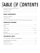
FEATURES / VOICE ARCHITECTURE .............................................................. ii IMPORTANT NOTES .................................................................................... 1 INTRODUCTION ......................................................................................... 2 BASIC OPERATION GETTING IT STARTED................................................................................... 3 CONNECTIONS ...........................................................................
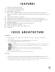
I. II. III. IV. V. VI. VII. VIII. IX. X. XI. XII. XIII. XIV. Portamento and auto glide. Single and multiple triggering. Inverting of envelopes 1 and 3. Note priority: low or last. LFO 2 sync to MIDI clock with seven beat divisions: whole, half, quarter, quarter note triplet, eighth, eighth note triplet, sixteenth, and sixteenth note triplet. Assignable additional envelope. Audio frequency modulation of Oscillator 1 and filter by Oscillator 2.
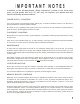
In addition to the aforementioned "Safety Instructions" printed on the inside front cover, we (the goodly folks at S. E.) ask––nay, we implore!––you please read and heed the following recommendations: POWER SUPPLY CONCERNS Turn off the power to all equipment before making any connections between devices. This will help to prevent malfunction and likely speaker damage.
Thank you for purchasing the S T UDIO E LECTRONICS ATC- X. You're soon to discover the world's only 4-way discrete multi-filtered analog synthesizer. Like never before, you now have the ability to create and explore all of the classic Analog synthesizer sounds in one powerfully expressive and versatile machine. The ATC- X is a truly modern Analog synthesizer, incorporating authentic discrete component circuitry with complete MIDI implementation and total programmability.
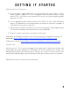
Setting Up the Instrument A. Plug the power supply cable into any conventional A.C. outlet. With its autoswitching power supply the ATC-X is capable of accommodating voltages ranging from 90 - 250. So, wherever you and your ATC-X are in this great big world, proper operation is a cinch. B. Use an appropriate patch-chord to connect the ATC-X to your sound monitoring devices. To reproduce the full sound spectrum of which the synthesizer is capable, a "high fidelity" P.A. system is required. C.
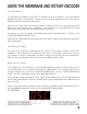
The Membrane The front panel membrane of the ATC–X contains an array of switches, with each colored pad located atop a single switch. To access any function or parameter; press with light to moderate force on the desired switch pad. Some of the switch pads have dual or multiple functions; which when pressed more than once access the next function. In addition, a few functions are accessed by pressing and holding one switch pad, then immediately pressing another.
The oscillators are the unmodified building blocks of Analog synthesis. An oscillator produces periodic or regularly repeating waveforms, i.e. pitched sounds. The tuning controls alter the frequency or pitch of the oscillators. The waveshape selectors determine the harmonic spectrum of the signal, its basic timbre, or tone color. The ATC-X 1 has two oscillators that each produce three waveforms.
What the Switch pads do: Selects the mix level of Oscillator 1. As the level is increased beyond 1 0 0 some harmonic distortion may occur; which is quite normal depending upon how many waveforms are selected and the settings of the filter. Selects the mix level of Oscillator 2 (same potential for harmonic distortion as Oscillator 1). Selects the mix level of the noise or distortion. Noise is a random signal, a rushing, static-like sound. The ATC-X's noise generator produces white noise.
The ATC-X with its unique interchangeable filter system features four classic wide range lowpass filters, and in the case of the MINI and 2600, "resonant" filters (see VOICE ARCHITECHURE). The Filter attenuates, or "cuts- off" the higher frequency components––those which lie above the adjustable cutoff frequency, and passes the lower frequency components of the audio signal.
The filter envelope shapes the timbre and overtone content of the audio signal as it passes through the modifying circuitry from the mixer. This envelope or "contour" generator is used to dynamically move the cutoff frequency. It works as such: each time a key is depressed an envelope or "contour” generator attached to the filter's cutoff frequency is actuated, and sends a control signal to the filter.
Envelope 2: VCA The volume of the audio signal, which passes through the VCA envelope, is contoured by the envelope controls. Each time a key is pressed, the envelope or "contour" generator attached to the amplifier is actuated, and sends a control signal to the amplifier. Like the filter envelope control signal, the VCA envelope control signal is composed of the same four segments: initial rise, decay, sustain level, and release time.
E n v e l o p e 3 : A ss i g n a b l e Envelope 3 can be assigned to modulate a variety of different parameters to create unusual textures and interesting effects. See the target list below for the parameters Envelope 3 can control. What the Switch pads do: The attack, decay, sustain, and release controls all function in the same manner for Envelope 3 as they do for the VCF and VCA envelopes.
Modulation is the use of a control signal to create a repetitive pattern of pitch, level, or harmonic content changes. The shape of the modulation is determined by the waveform that the LFO outputs––selected by the wa v e switch pad. In addition to the four selectable waveshapes, sample & hold and noise provide random modulation. The amount of modulation is determined by either the depth control or any assigned MIDI controller.
Selects LFO 1 and 2 waveforms. Press once for LFO 1 waveform selection, press again for LFO 2 waveform selection. Continuous presses will toggle the LFOs (see the "QUICK REFERENCE GUIDE" sheet for waveform number definitions). Void below vintage NAMM Show banner reserved for doodling, grease stains and sectional integrity (by mercurial order of the Knights Regis). May it serve and soothe you well. Pimp your wall: full-sized, color banner art available at: http://studioelectronics.
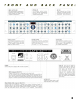
The ATC-X is completely controllable by MIDI, with a long list of parameters and functions assignable to Velocity, Modwheel, and Aftertouch. Certain sound parameters also have a dedicated Continuous Controller assignment (see chart on page 16). In addition, parameter edits made by the rotary encoder are transmitted as Controller data. This extensive MIDI implementation allows for an almost unlimited expression of tone and timbre manipulation, which can be recorded to any MIDI sequencer.
Selects the MIDI clock assignment to LFO 2. The rate of LFO 2 can be synchronized to incoming MIDI time clock sent from your sequencer. The beat divisions available are: 1 = whole note, 2 = half note, 4 = quarter note, 4 - 3 = quarter note triplet, 8 = eighth note, 8 - 3 = eighth note triplet, 1 6 = sixteenth note, 1 6 - 3 = sixteenth note triplet. Note: LFO 2 rate control will not respond when a MIDI clock division is selected. Selects the master tuning and overall transpose.
Located in this section is the display and rotary encoder, which along with the membrane front panel, makeup the user interface. Playing and programming the ATC-X involves two basic modes of operation: Patch Play Mode and Edit Mode. In Patch Play mode, the unit will cycle through its 512 patches when the encoder is turned. The ATCX enters Edit Mode when any parameter or function of a patch is selected, at which the edit periods will appear.
Osc 1&2 freq VCF freq VCF res Osc 1 freq Env 1 amnt Env 2 amnt Env 3 amnt VCF freq VCF res Osc 1 freq 54 Osc 1 freq 55 Osc 1 tri on / off 56 Osc 1 saw on / off 57 Osc 1 pul on / off 58 Osc 1 pul width 59 Osc 2 freq 60 Osc 2 tri on / off 61 Osc 2 saw on / off 62 Osc 2 pul on / off 63 Osc 2 pul width 70 LFO 1 rate 71 LFO 1 depth 72 LFO 2 rate Bank select** 7 Volume Osc 1mix Osc 1 PW Osc 2 freq Osc 2 mix VCF freq VCF res Osc 1 freq Osc 1 mix Osc 1 PW Osc 2 freq Osc 2 mix Osc 2 PW X mod amount Noise mix L
Studio Electronics ATC-X Basic Channel Mode Note Number Velocity After Touch MIDI Implementation Chart Function*** Default Changed Default Messages Altered True Voice Note ON Note OFF Key's Ch's Pitch Bend Control Basic Channel Change (see chart pg. 15) Program True # Change System Exclusive System Common Transmitted X X X Recognized 1-16 1-16 4 X X 0-127 X X X X 09n. V=127 X O O X 0-127 O O December 30, 2007 Version 2.
Maximum voices: one Parameter resolution: 16 bit Display: 3 digit light emitting diodes Sound memory: internal RAM, 512 patches Frequency response: very low to dog bothering Residual noise level: really quiet Total harmonic distortion: not much, but just enough External dimensions: 19" x 10" x 31/2" (2 rack spaces) Output: -15 dbm Power supply: AC 90 - 250 VAC (50/60hz) auto switching Weight: 8lbs of expertly designed well wrought genius CV out: 0 - 10 volts / Gate out: 10 volt posi