STUDER Innotec Xtender INSTALLATION AND OPERATING INSTRUCTIONS Unit combining inverter, battery charger and transfer system. Xtender XTH 3000-12 XTH 5000-24 XTH 6000-48 XTH 8000-48 + BTS-01 temperature sensor STUDER Innotec Rue des Casernes 57 CH – 1950 Sion Tel. +41 (0)27 205 60 80 Fax. +41 (0)27 205 60 88 Installation and operating Instructions Customer service: Sales department: Technical assistance: Website: Xtender V1.3 info@studer-innotec.com sales@studer-innotec.com support@studer-innotec.
STUDER Innotec Xtender TABLE OF CONTENTS 1 2 2.1 2.2 2.3 2.4 3 3.1 3.2 3.3 3.4 3.5 3.6 4 4.1 4.2 4.3 4.4 4.5 5 6 6.1 6.2 6.3 6.4 7 7.1 7.2 8 9 10 11 12 13 14 15 16 17 18 INTRODUCTION ................................................................................................................ 3 GENERAL INFORMATION................................................................................................ 3 Operating instructions.................................................................
STUDER Innotec Xtender 1 Introduction Congratulations! You are about to install and use a device from the Xtender range. You have chosen a high-tech device that will play a central role in energy saving for your electrical installation. The Xtender has been designed to work as an inverter / charger with advanced functions, which can be used in a completely modular way and guarantee the faultless functioning of your energy system.
STUDER Innotec Xtender 2.2 Conventions This symbol is used to indicate the presence of a dangerous voltage that is sufficient to constitute a risk of electric shock. This symbol is used to indicate a risk of material damage. This symbol is used to indicate information that is important or which serves to optimise your system. All values mentioned hereafter, followed by a configuration no. indicate that this value may be modified with the help of the RCC-02/03 remote control.
STUDER Innotec Xtender 2.3.2 EXCLUSION OF LIABILITY The placement, commissioning, use, maintenance and servicing of the Xtender cannot be the subject of monitoring by Studer Innotec. For this reasons we assume no responsibility and liability for damage, costs or losses resulting from an installation that does not conform to the instructions, defective functioning or deficient maintenance. The use of a Studer Innotec inverter is the responsibility of the customer in all cases.
STUDER Innotec Xtender Never try to charge frozen batteries. When working with the batteries, a second person must be present in order to lend assistance in the event of problems. Sufficient fresh water and soap must be kept to hand to allow adequate and immediate washing of the skin or eyes affected by accidental contact with the acid. In the event of accidental contact of the eyes with acid, they must be washed carefully with cold water for 15 minutes. Then immediately consult a doctor.
STUDER Innotec Xtender 3.5 Fastening The Xtender is a heavy unit and must be mounted to a wall designed to bear such a load. A simple wooden panel is insufficient. The Xtender must be installed vertically with sufficient space around it to guarantee adequate ventilation of the device (see figs. 2a and 2b). If the Xtender is installed in a closed cabinet this must have sufficient ventilation to guarantee an ambient temperature that conforms to the operation of the Xtender.
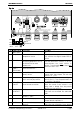
STUDER Innotec Xtender Fig. 4a 11 12 13 8 1 2 7 123 5 A B 6 10 L AC Input AUX1 2 1 3 L1 L2 L3 AUXILLARY CONTACT AUX2 14 9 ! L AC Output Warning! Check battery polarity (+/-) before connecting A wrong connexion may damage the systen 4 OFF Open ON Main switch Temp. Sens. Terminated Pos. Denomination Description 1 ON/OFF Main on/off switch Main switch 2 Temp. Sens Connector for the battery temperature sensor 3 Com.
STUDER Innotec 12 -BAT 13 AC Input 14 AC Output Xtender Negative pole battery connection terminals Connection terminals for the alternative power supply (generator or public network) Connection terminals for the device output. and when tightening the clamp. See chapter 4.5.7 - p. 14. Note: It is imperative that the PE terminal be connected. See chapter 4.5.6 - p. 14. Note: Increased voltages may appear on the terminals, even in the absence of voltage at the input of the inverter.
STUDER Innotec Xtender vehicles and leisure vehicles. In these cases, two separate AC inputs are often required, one connected to the grid and the other connected to an on-board generator. Switching between two sources must be carried out using an automatic or manual reversing switch, conforming to the applicable local regulations. The Xtender has a single AC input. Various application examples are described in figs. 10a – 10b – 10c). 4.1.
STUDER Innotec Xtender This connection (C) is not permitted if a socket is installed upstream of the Xtender. 4.2.3 INSTALLATION WITH AUTOMATIC PE-NEUTRAL SWITCHING In certain applications, it is desirable to keep the neutral upstream and downstream of the Xtender separated (C) while reestablishing the earthing system (TN-S, TT or TNC-S) in the absence of voltage at the input. This can be programmed by the configuration {1485} via the RCC-02/03 remote control.
STUDER Innotec Xtender 4.3.4 DIMENSIONING THE ALTERNATIVE ENERGY SOURCES In a hybrid system, the alternative energy sources such as the solar generator, wind power and small hydropower should, in principle, be dimensioned in such a way as to be able to cover the average daily consumption. 4.4 Wiring diagrams The diagrams shown in the appendix of this document are subsidiary. The applicable local installation regulations and standards must be adhered to.
STUDER Innotec Xtender 4.5.4 BATTERY-SIDE CONNECTION Before connecting the battery, carefully check the voltage and polarity of the battery using a voltmeter. Incorrect polarity or surge voltage may seriously damage the device. Prepare the batteries for connection: appropriate battery clamps, protection device (f), cable in good conditions with correctly fitted clamps. Fasten the negative cable on to the negative pole (-) of the battery and the positive cable on the open protection device (f).
STUDER Innotec Xtender 4.5.6 CONNECTING THE CONSUMERS AT THE 230 V AC OUTPUT High voltages may be present on the connection terminals (13) and (14). Make sure that the inverter is deactivated and that there is no AC or DC voltage present on the AC IN terminals and battery terminals, before proceeding with the connection.
STUDER Innotec Xtender The length of the communication bus cable must not exceed 300 m. In a system comprising a single Xtender, the connection of the RCC-02 or RCC-03 may be conducted without stopping the Xtender (warm). The communication bus will be used to interconnect other Xtender inverters in the case of a multiunit application or to connect other types of users who have the proprietary protocol of Studer Innotec.
STUDER Innotec Xtender 6 Description and functioning The Xtender is a sine wave inverter with a battery charger. It has been developed for use as a standalone installation to supply AC voltage (not connected to the grid) or as a continuous supply. 6.
STUDER Innotec Xtender range {1187} by means of the RCC-02/03 remote control. When the configuration is set to 0 the inverter will still operate even in the absence of any consumer. When the load search sensitivity {1187} is set to 0 in a paralleled multi-units system, the master/slave behaviour is inhibited and all the inverter will be always functional whatever the load is. In standby mode the system will thus consume minimal power from the battery (see table of technical data p. 36). 6.2.
STUDER Innotec Xtender The charge cycle, programmed by default, as shown in the example described in the figure opposite, runs automatically. The line (28) indicates the development of the battery voltage. The lower line (29) indicates the battery current (input and output). ACin=OK {1138} {1156} {1140} {1159} 28 29 The cycle starts with a continuous current a e d charge (a) adjusted by default according to the configuration {1138}.
STUDER Innotec Xtender Much more complex charge profiles or exclusion of the charger can be configured using the RCC-03/03 remote control. Configuration of the battery is the responsibility of the operator. Incorrect configuration that does not correspond to the charging methods of the battery recommended by the manufacturer may be dangerous and/or considerably diminish the battery service life.
STUDER Innotec Xtender control is required. When this function is activated {1126}, it allows the current from the battery to be supplied to the user in order to guarantee that the current at the input of the device does not exceed the limit set {1107}. If the input current limit is exceeded, the transfer relay will be opened immediately, thereby protecting the upstream protection device.
STUDER Innotec Xtender A battery voltage greater than 1.66 x the nominal voltage may lead to significant damage or destroy the device. Overheating of the Xtender, Insufficient ventilation, increased ambient temperature or obstructed ventilation may lead to overheating of certain internal components of the unit. In this case, the device will automatically limit its power output as long as this abnormal situation persists.
STUDER Innotec Xtender 6.3 Multi-unit configurations Several Xtenders can be used in the same system, either to create a three-phase system or to increase the power output of a single or two phases. The implementation of this configuration requires particular precautions and it must be installed and commissioned by qualified personnel only. When multi-unit system is commissioned, the software's version of every units will be automatically checked and units may refuse to start in case of incompatibility.
STUDER Innotec Xtender 6.4 Accessories 6.4.1 CONTROL CENTRE AND RCC-02/03 (REMOTE CONTROL) DISPLAY An RCC-02/03 remote display and programming unit can be optionally connected to the Xtender via one of the two RJ45-8-type “Com. Bus” (3) connectors. These connectors may only be used for connecting a CAN-ST compatible accessory, excluding any other connection such as LAN, Ethernet, ISDN, etc. The RCC-02/03 control centre is vital for modifying device configurations.
STUDER Innotec Xtender 6.4.2 BTS-01 TEMPERATURE SENSOR The operating voltages for lead batteries vary depending on the temperature. A temperature sensor is optionally available to correct the battery voltage and guarantee an optimum charge whatever the battery temperature. The correction factor given by the correction of the sensor is set by the configuration {1139} Article no. for the temperature sensor (including a cable of 3 m): BTS-01. Dimensions: H x W x D / / 58 x 51.5 x 22 mm 7 Control 7.
STUDER Innotec Xtender In this event the equipment will make several attempts restart {1133} every few seconds and will stop if the overload remains (see chap. 6.2.9 – p. 20). It is vital to eliminate the cause of the overload without restarting. Restarting is carried out manually by pressing the button (41).
STUDER Innotec Xtender 8 Maintenance of the installation With the exception of the periodic checking of connections (tightening and general condition) the Xtender does not require any special maintenance. 9 Product recycling The models of the Xtender series conform to the European directive 2002/95/EC on hazardous substances and does not contain the following elements: lead, cadmium, mercury, hexavalent chrome, PBB or PBDE.
STUDER Innotec Xtender 11 Comments of annexes’ figures Fig. 1a 1b 2a 2b 3a 3b 4a 4b 5a 5b 5c 5d 6a 6b 6c 6d 7 8a 8b 8c 9a 9b Description and comment Dimensioning table for the downstream protection device (F). See chap. 4.5.6 – p.14. Type plate and series no. See chapter 16 - p. 32. The intactness of this label is vital for any possible warranty claims. It must not be altered or removed.
STUDER Innotec Fig. 10a 10b 10c 11 12 13 14 15 Xtender Description and comment Example of installation in a vehicle (AC part) Special features: The connection of the neutral (C) is not permitted (presence of a socket upstream). The earth-neutral connection is absent in inverter mode (neutral stand-alone system). The safety is guaranteed by the equipotential bonding (frame). The automatic reestablishment of the earth-neutral connection downstream of the device in inverter mode can be programmed.
STUDER Innotec Fig. 16 17 18 19 Xtender Description and comment Example of cabling of 9 Xtenders in three-phase and parallel – AC part Special feature: In fixed high power installations, it is advised that a shared neutral be retained, distributed to all parties in the grid (see (C)) The comments for figs. 12 to 15 are valid.
STUDER Innotec Xtender 13 Figure element's (AC part) Elem. Description A Input supply cable B C D E F G H J K L P R S Comment The section is determined by means of the maximum current at source and the protection device (H). In multi-unit systems, cables (A) of the same phase must have the same length and section (see comment fig. 12-2/3). Output cable supply In multi-unit systems, cables (B) of the same phase must have the same length and section (see comment fig. 12-2/3).
STUDER Innotec Xtender Elem. Description T Non-secured grid U V W X Y Comment Distribution to users supplied exclusively via the present grid or the generator. This distribution is carried out in conformity with the local standards and regulations. Public grid The connection to the public grid imposes adherence to the local standards and regulations at the responsibility of the installer. The installation should, in principle, be checked and approved by an official body.
STUDER Innotec Xtender Pos. Denomination Description 10 L1/L2/L3 Phase selection jumpers. 11 +BAT 12 -BAT 13 AC Input 14 AC Output Comment See chapter 6.3.1. – p.22. Jumper default at position L1 Positive pole battery connection Carefully read chapter 4.5 – p.12 Take care with the polarity of the battery terminals Negative pole battery and when tightening the clamp. connection terminals Connection terminals for the See chapter 4.5.7 - p. 14.
STUDER Innotec Xtender Pos. Denomination 33 U Battery Description Rated battery voltage (input area) 34 U ACin Rated AC input voltage (input area) 35 I ACin/out Maximum current at input / output 36 37 U ACout I Charge Rated output voltage Maximum charger current 38 39 SN:xxxxxxxxxx IPxx Serial no. Protection degree according to IEC 60529 Installation and operating Instructions Xtender V1.3 Comments See chapter 6.2.8– p. 20 See chapter 6.2.3 – p. 17 See chapter 6.2.6 - p. 19.
STUDER Innotec Xtender 17 Table of standard configurations No. of Denomination / description config. Units Fact. Mod.
STUDER Innotec Xtender No. of Denomination / description config. Units Fact. Mod. value value 1298 1300 1303 1304 1307 1309 1403 1404 1432 1433 mV/cell ---V/cell Vac sec. sec. Vac V 20 3 3 3 2.2 185 60 0 270 20 y/n Vac y/n V/cell Hz Hz y/n y/n o/n Min. Auto/Man yes 10 no 1.
STUDER Innotec Xtender 18 Technical data Model XTH 3000-12 XTH 5000-24 XTH 6000-48 XTH 8000-48 Inverter Rated battery voltage 12 V 24 V 48 V 48 V Input voltage range 9.