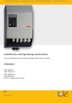
PHOTOVOLTAIK - PHOTOVOLTAIC - PHOTOVOLTAIQUE - FOTOVOLTAICA Installation and Operating Instructions Unit combining inverter, battery charger and transfer system. Xtender XTH 3000-12 XTH 5000-24 XTH 6000-48 XTH 8000-48 BTS-01 temperature sensor EN 723.932 | V 0.
Steca Xtender TABLE OF CONTENTS 1 2 2.1 2.2 2.3 2.4 3 3.1 3.2 3.3 3.4 3.5 3.6 4 4.1 4.2 4.3 4.4 4.5 5 6 6.1 6.2 6.3 6.4 7 7.1 7.2 8 8.1 9 10 11 12 13 14 15 INTRODUCTION ................................................................................................................ 3 GENERAL INFORMATION................................................................................................ 4 Operating instructions..............................................................................
Steca Xtender 1 Introduction Congratulations! You are about to install and use a device from the Xtender range. You have chosen a high-tech device that will play a central role in energy saving for your electrical installation. The Xtender has been designed to work as an inverter / charger with advanced functions, which can be used in a completely modular way and guarantee the faultless functioning of your energy system.
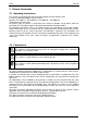
Steca Xtender 2 General information 2.1 Operating instructions This manual is an integral part of each inverter/charger from the Xtender series. It covers the following models and accessories: Xtender: XTH 3000-12 – XTH 5000-24 – XTH 6000-48 – XTH 8000-48 Temperature sensor: BTS-01 For greater clarity, the device is referred to in this manual as Xtender, unit or device, when the description of its functioning applies indiscriminately to different Xtender models.
Steca Xtender 2.3 Quality and warranty During the production and assembly of the Xtender, each unit undergoes several checks and tests. These are carried out with strict adherence to the established procedures. Each Xtender has a serial number allowing complete follow-up on the checks, according to the particular data for each device. For this reason it is very important never to remove the type plate (appendix I – fig. 3b) which shows the serial number.
Steca Xtender DC voltage coming from the battery as well as the source of AC voltage coming from a generator or network have been disconnected from the electrical installation. Even when the Xtender has been disconnected from the supply sources (AC and DC), a dangerous voltage may remain at the outputs. To eliminate this risk you must switch the Xtender OFF using the ON/OFF button (1). After 10 seconds the electronics is discharged and intervention may take place without any danger.
Steca Xtender 3.3 Unpacking When unpacking, check that the equipment has not been damaged during transportation and that all accessories listed below are present. Any fault must be indicated immediately to the product distributor or the contact given at the back of this manual. Check the packaging and the Xtender carefully. Standard accessories: Installation and operating instructions, c.f. Appendix 1 Mounting plate – fig. 2a (18) 2 conduit glands for the battery cable 3.
Steca Xtender 3.6 Connections 3.6.1 GENERAL RECOMMENDATIONS The Xtender falls within protection class I (has a PE connection terminal). It is vital that a protective earth is connected to the AC IN and/or AC OUT PE terminals. An additional protective earth is located between the two fastening screws at the bottom of the unit (fig. 2b-(17)).
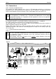
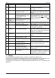
Steca Xtender Pos. Denominati on 1 ON/OFF Main switch Description Comment Main on/off switch 2 Temp. Sens Connector for the battery temperature sensor 3 Com. Bus 4 5 O/T (Open / Terminated) -- Double connector for connecting peripherals such as the RCC002/03 or other Xtender units Switch for terminating the communication bus. See chapter Automatic load shedding of the inverter (2 sequences) 7.1 – p 26. See chapter 6.2.11 – p. 23. Only connect the original Steca BTS-01 sensor See chapter 4.5.
Steca Xtender 4.1 Choice of system The Xtender may be used in different system types, each of which must meet the standards and particular requirements associated with the application or site of installation. Only an appropriately qualified installer can advise you effectively on the applicable standards with regard to the various systems and the country concerned. Examples of cabling are presented in appendix I of this manual, fig. 5 and following.
Steca Xtender 4.2 Earthing system The Xtender is a protection class I unit, which is intended for cabling in a grid type TT, TN-S or TNC-S. The earthing of the neutral conductor (E) is carried out at a sole installation point, upstream of the RCD circuit breaker (D). The Xtender can be operated with any earthing system. In all cases it is imperative that the protective earth be connected in compliance with the applicable standards and regulations.
Steca Xtender 4.3 Recommendations for dimensioning the system 4.3.1 DIMENSIONING THE BATTERY The battery capacity is dimensioned according to the requirements of the user – that is 5 to 10 times its average daily consumption. The discharge depth of the battery will therefore be limited and the service life of the battery will be extended. On the other hand, the Xtender must have a battery capacity that is large enough to be able to take full advantage of the performance of the equipment.
Steca Xtender 4.5 Connecting the battery Lead batteries are usually available in 2 V, 6 V or 12 V block types. In the majority of cases, in order to obtain an operating voltage that is correct for Xtender usage, several batteries must be connected in series or in parallel depending on the circumstances. . In multi-unit systems, all Xtenders from the same system must be connected according to the same battery bank.
Steca 4.5.3 Xtender BATTERY-SIDE CONNECTION Before connecting the battery, carefully check the voltage and polarity of the battery using a voltmeter. Incorrect polarity or surge voltage may seriously damage the device. Prepare the batteries for connection: appropriate battery clamps, protection device (f), cable in good conditions with correctly fitted clamps. Fasten the black cable on to the negative pole (-) of the battery and the red cable on the open protection device (f).
Steca Xtender 4.5.4 EARTHING THE BATTERY One of the two battery conductors can be earthed. This may be either the positive or negative pole. In all cases the installation must conform to the local regulations and usage or specific standards associated with the application. In case of earthing, the earthing conductor section must at least be equivalent to the section of the battery conductor. The earthing of the equipment must also adhere to these regulations.
Steca Xtender 4.5.6 CONNECTING THE AC SUPPLY SOURCES The Xtender is intended to be supplied by alternative voltage sources such as the public grid or a generator. Check that the rated voltage of the source corresponds to the rated voltage (34) of the Xtender specified on the type plate (fig. 3b).
Steca Xtender 5 Energisation of the installation It is imperative that the closing cap for the connection compartment be installed and screwed tight before the installation is energised. There are dangerous voltages within the interior of the connection compartment. The connection of the Xtender must be carried out in the order given below. Any disassembly must be carried out in the reverse order. 1. Connecting the battery Too high or inappropriate a battery voltage may seriously damage the Xtender.
Steca Xtender 6 Description and functioning The Xtender is a sine wave inverter with a battery charger. It has been developed for use as a standalone installation to supply AC voltage (not connected to the grid) or as a continuous supply. 6.1 Circuit diagram 17 AC IN 100nF 2,2nF AC OUT K1 2,2nF K3 K4 2,2nF 2,2nF K2 Aux1 Aux2 14 13 f 10nF 10nF AC DC t 9 12 BTS-01 f 10 AC out 1x AC in 1x Charge 1x 2x ON 1x 6 RJ45 1x Battery low 2x 3x 4x O RJ11 6p 8p 8p Swiss Made Temp.
Steca Xtender technical data p. 37). The detection threshold for the absence of loads can be adjusted according to the configuration range {1187} by means of the RCC-02/03 remote control. When the configuration is set to 0 the inverter will still operate even in the absence of any consumer. 6.2.3 TRANSFER RELAY The Xtender can be connected to an alternative power source such as a generator or public network.
Steca Xtender The charge cycle, programmed by default, ACin=OK as shown in the example described in the figure opposite, runs automatically. {1138} The line (28) indicates the development of {1156} the battery voltage. {1140} The lower line (29) indicates the battery 28 {1159} current (input and output). The cycle starts with a continuous current 29 charge (a) adjusted by default according a e d to the configuration {1138}.
Steca Xtender If the BTS-01 temperature sensor is used, the voltage adjustment thresholds for the battery are corrected in real time by means of the battery temperature. The value of this correction is set by the configuration {1139} in the configuration table p. 35. Much more complex charge profiles or exclusion of the charger can be configured using the RCC-02/03 remote control. Configuration of the battery is the responsibility of the operator.
Steca Xtender When this function is activated, the battery can be fully discharged despite the presence of the grid or the generator. The average power consumed by the user must not exceed the power of the source, at the risk of discharging the battery. The smart boost function is deactivated by default. To activate the function the RCC-02/03 remote control is required.
Steca Xtender Overheating of the Xtender: Insufficient ventilation, increased ambient temperature or obstructed ventilation may lead to overheating of certain internal components of the unit. In this case, the device will automatically limit its power output as long as this abnormal situation persists. The Xtender is protected by the internal fuse from incorrect polarity (24 V and 28 V versions). The Xtender XTH-3000-12 does not have an internal fuse and can be protected by an external 400 A fuse. 6.2.
Steca Xtender Interrupting this connection in a multi-unit system will lead to the stoppage – after 5 seconds – of all the units in the system. Various application examples are described from fig. 12 to fig. 19. It is important to read and adhere to the descriptions associated with each of the figures mentioned above In configurations carrying several Xtenders, each unit is controlled independently using the ON/OFF push button (41).
Steca Xtender The features of the RCC-02 and the RCC-03 are the same. They only differ in their external appearance. The RCC-02 is designed for wall mounting, whereas the RCC-03 is designed as a tabletop device. The RCC-03 model must be taken off the table to allow access to the SD card slot (during updating, for example). RCC-02: Dimensions: H x W x D / / 58 x 51.5 x 22 mm RCC-03: Dimensions: H x W x D / / 58 x 51.5 x 22 mm The two remote control models are delivered with a 2 m cable by default.
Steca Xtender 7 Control 7.1 Main on/off control This switch (1) interrupts the electronic supply and all the Xtender peripherals. The residual consumption on the battery is therefore less than 1 mA. The ON/OFF switch is used only for the complete stoppage of the whole system. 7.2 Display and control parts The Xtender has a ON/OFF button and light indicators at the front of the device, allowing clear identification of the operating mode.
Steca Xtender 5x No transfer. Insufficient In this case, the Xtender remains in operation in inverter power from the source mode and does not allow the transfer relay to close. You must increase the input current limit {1107}, or authorise the exceeding of this limit {1436} or authorise backup on the source {1126}, or disconnect some consumers (decrease of loads). 6x Startup prevented due to Voltage is present at the device output.
Steca Xtender 8 Maintenance of the installation With the exception of the periodic checking of connections (tightening and general condition) the Xtender does not require any special maintenance. 8.1 Product recycling The models of the Xtender series conform to the European directive 2002/95/EC on hazardous substances and does not contain the following elements: lead, cadmium, mercury, hexavalent chrome, PBB or PBDE.
Steca Xtender 10 Figure comment tables Fig. Description and comment 1a Dimensioning table for the downstream protection device (F). See chap. 4.5.5 – p. 15. 1b Assembly order for connecting the battery. The assembly order for the battery connections must be adhered to.
Steca Xtender Fig. Description and comment 9a Fixed installation with plug connection to the single-phase source – AC part Special feature: The connection of the neutral upstream and downstream of the Xtender (C) is prohibited in this configuration (presence of a plug upstream). See also chapter 6.2.11 – p. 23.
Steca Xtender Fig. Description and comment 16 Example of cabling of 9 Xtenders in three-phase and parallel – AC part Special feature: In fixed high power installations, it is advised that a shared neutral be retained, distributed to all parties in the grid (see (C)) The comments for figs. 12 to 15 are valid.
Steca Xtender Elem. Description Comment A Input supply cable The section is determined by means of the maximum current at source and the protection device (H). In multi-unit systems, cables (A) of the same phase must have the same length and section (see comment fig. 12-2/3).
Steca Xtender Elem. Description T Non-secured grid U Public grid V Automatic earthneutral connection W Galvanic isolator X Source reversing switch Y Isolation transformer Comment Distribution to users supplied exclusively via the present grid or the generator. This distribution is carried out in conformity with the local standards and regulations. The connection to the public grid imposes adherence to the local standards and regulations at the responsibility of the installer.
Steca Xtender 12 Control and display parts for the Xtender (fig. 4b) See chapter 7.1 - p. 26. Pos.
Steca Xtender 14 Table of standard configurations No. of config. 1107 1108 1109 1110 1111 1111 1112 1121 1126 1133 1138 1139 1140 1156 1157 1159 1187 1190 1191 1198 1199 1200 1300 1303 1304 1309 1403 1404 1432 1436 1470 1485 1488 1505 1506 1286 Denomination / description Fact. Mod. G1 G2 G3 valuevalue 1 2 3 kVA kVA kVA 3.5 7 12 Maximum current of the AC source A 30 Undervoltage of the empty battery V/cell 1.9 Sub-voltage of the charged battery V/cell 1.
Steca Xtender To modify the configurations, please refer to the operating instructions for the RCC02/03 remote control Installation and Operating Instructions 723.932 Xtender V0.
Steca Xtender 15 Technical data Model XTH 3000-12 XTH 5000-24 XTH 6000-48 XTH 8000-48 Inverter Rated battery voltage 12 V 24 V 48 V 48 V Input voltage range 9.
Steca Installation and Operating Instructions 723.932 Xtender V0.
Steca Installation and Operating Instructions 723.932 Xtender V0.
723932