STUDER INNOTEC XP-COMPACT User and installer Manual Combi Inverter, Battery charger and Transfersystem XP-COMPACT XPC 1112 XP-COMPACT XPC 1624 XP-COMPACT XPC 1648 Remote control RCC-01 Temperature sensor CT-35 Solar charge controller XPCxxxx-S AC cable cover CFC-01 IP-23 top cover C-IP23 STUDER INNOTEC Rue des Casernes 57 CH-1950 SION User manual TEL: ++41 (0)27 205 60 80 FAX: ++41 (0)27 205 60 88 EMAIL : info@studer-inno.com XP-COMPACT V2.
STUDER INNOTEC XP-COMPACT Summary 1 General Information .................................................................................................................3 1.1 1.2 1.3 1.4 1.5 1.6 2 OPERATING INSTRUCTIONS ................................................................................................................................3 QUALITY AND WARRANTY.................................................................................................................................
STUDER INNOTEC XP-COMPACT 4.8.3 Delayed mode of the Transfer System .........................................................................................................15 4.9 THE SOLAR CHARGE CONTROLLER (OPTION)....................................................................................................15 4.10 THE MULTIFUNCTIONAL CONTACT ..................................................................................................................16 4.11 THE TEMPERATURE SENSOR .............
STUDER INNOTEC XP-COMPACT 1 General Information 1.1 Operating instructions This manual is a part of the delivery package of every XP-COMPACT inverter-charger. It serves as guidelines for safe and efficient operation of XP-COMPACT. The instructions are only valid for use with the following appliances and options: - XP-COMPACT XPC1112 - XP-COMPACT XPC1624 - XP-COMPACT XPC1648 - Temperature sensor CT-35 Remote control RCC-01 Solar charge controller.
STUDER INNOTEC 1.5 XP-COMPACT Precautions This manual must be readily available for the user at all times. The user must be familiar with the precautions and safety aspects. During operation of XP-COMPACT, high voltages are generated at the connections and inside of the appliance which could be deadly fatal. Work on the appliance and on the installation should only be carried out by qualified and trained personnel.
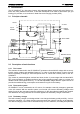
STUDER INNOTEC XP-COMPACT 2 Introduction The XP-COMPACT is a sine wave inverter with integrated battery charger and solar charge controller with many additional functions, it has been developed to be used as stand-alone (no grid feeding) AC provider, or as continuous / break-free current supply provider (UPS). 2.1 Principle schematic AC IN Input 100nF PE 230Vac 10nF 1uF L PE Output N 10nF Filter 4x2,7MΩ CT35 Temp.
STUDER INNOTEC XP-COMPACT technical specification (chap.6). The battery charger is meant for the lead-acid and lead-gel batteries. Thanks to the floating charge system the battery can remain continuously connected. 2.2.4 The solar charge controller (optional) With the built-in solar charge controller, the XP-COMPACT is a complete solar-power-center. In a solar installation this controller ensures that the batteries are charged correctly.
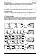
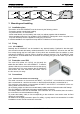
STUDER INNOTEC 2.3.3 XP-COMPACT Connection in parallel and in serie 12V 12V 12V 12V 24V 3 Mounting and installing 3.1 Installation place The location of the XP-COMPACT must be chosen by the following criteria: - Protection against unauthorized handling - Dry dust free room, no condensation - Never install directly over the battery and never in a cabinet together with the batteries - Keep ventilation holes free.
STUDER INNOTEC XP-COMPACT Connecting must be done by qualified staff. Material such as cable, connectors and distribution boxes, fuses etc. used in the installation must comply with the respective valid low-voltage installation rules and regulations. 3.4.2 Protection cover for the terminals connections The protection cover is available in option (Order ref. CFC-01) and avoids to do wrong hazardous contact on the terminals 230Vac. It is mounted with strain relief clamps for the cable. 3.
STUDER INNOTEC 3.6 XP-COMPACT Cabling/wiring Connecting of the XP-COMPACT is a very important step in the installation. You must take care that all connecting work is carried out in a clean and correct manner and that under no circumstance a cable is connected to a wrong terminal. Connecting of the XP-COMPACT must be carried out in the following order. In case of dismantling this order must be reversed. 3.6.
STUDER INNOTEC XP-COMPACT 3.6.6 Connection to Auxiliary Contact On these three terminals is a potential free change-over contact. The maximal permitted current and voltage for this is 16A/250Vac. The LED 5 “Contact active” shows the position of them: alight means active and off means non-active. The schematic view of the connections on the front shows the relay in the non-active mode. 3.5.
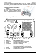
STUDER INNOTEC Display and control parameters on remote control panel (optional) COMPACT INVERTER - CHARGER TRANSFER 8 AC IN AC OUT 2 7 9 CHARGER SOLAR CHARGE INVERTER 14 4 Program 15 5 Contact active 16 6 Contact manual 17 RCC-01 90 160 80 130 70 100 60 80 50 60 40 40 Over Temp.
STUDER INNOTEC 13 OFF XP-COMPACT XP-COMPACT is turned off. Turn- XP-COMPACT is for the time being turned off. Turning it back on ing it back on is only possible will follow automatically! manually. 14 Battery Charger and/or Solar Charge Controller are doing an equalization cycle 15-18* Charge condition of Battery 25* CURRENT MONITOR LED 15 – Absorption time is running Display the value of the output power in % of Pnom (in Inverter Mode) and the charge current in Amps. (in Charger Mode) 4.
STUDER INNOTEC XP-COMPACT perature synchronizes the relay with the alarm signal. In this way, for example, an emergency back up system can be started without any break in the energy supply. 4.6.4 Battery Condition Deep discharging of the lead-acid batteries leads to high losses in capacity and early aging. This is why battery condition is continuously controlled and supervised. With low voltage the inverter switches off. The LED 12 „L/H Batt.“ is lit and the LED 13 „OFF“ blinks.
STUDER INNOTEC XP-COMPACT 4.7.2 Equalization charging Before you program the XP-COMPACT for Equalization-charge you must check with your supplier that the batteries are suitable for this process. Equalization is recommended for the lead-acid batteries in order to mix well the electrolyte fluid and to clean the lead plates.
STUDER INNOTEC XP-COMPACT the transfer contact is active, then you have at the output AC OUT the same voltage as that at the input. This voltage can not be modified by the XP-COMPACT! 4.8.1 Set the transfer voltage threshold The voltage threshold of the transfer is factory settled at 200Vac. This value is acceptable in most application. However, this value can be adjusted fro 150 to 230Vac if necessary.
STUDER INNOTEC XP-COMPACT 4.10 The Multifunctional Contact In the XP-COMPACT there is a built-in power relay. The potential-free change-over contact (NO – NC) of this power relay is connected to the screw terminal AUX CONTACT. Maximum Contact load: 230Vac /12Vdc/24Vdc/16Amp 60Vdc/3 Amp. ! The contact is activated when the XP-COMPACT is halted or by a fault condition, or by a normal manual stop done by pushing push-button 19.
STUDER INNOTEC 5.3 XP-COMPACT Battery Condition Built-in microprocessor calculates the actual state of charge of the battery and displays it on LED 15 – 18. The LED 14 is lit when the system is carrying out a charge cycle with equalization. The voltage levels and charge characteristics can be changed through Programming. The instruction for programming of battery levels is in the section „Programming” 5.4 Fault indicator 5.4.1 Overtemp.
STUDER INNOTEC 6.1 XP-COMPACT Standard setting The XP-COMPACT is delivered with the following default setting: 6.1.1 Battery voltage Low voltage Float Charge End of Charge Voltage Equalization Absorption Time: 11.6V / 23.2V / 46.4V 13.5V / 27.0V / 54.0V 14.4V / 28.8V / 57.6V 15.3V / 30.6V / 61.2V 2 Hours 6.1.2 Auxiliary contact Active in case of defect or manual turn off with the LED 10/11/12/13 6.
STUDER INNOTEC XP-COMPACT table 6.3.1. If desired, repeat the operation with any other parameter (voltage or time) to be changed. If during 10 seconds no buttons are pressed, the selected values are automatically stored and the XP-COMPACT switches back in to the normal operating status.
STUDER INNOTEC XP-COMPACT 6.4.3.3 Second priority cut-off The Auxiliary Contact can use to cut-off second priority load with the criteria of the battery status or overtemp. One of the 4 LED 15 to 18 or 10 will be chosen as the cut off criteria. The second priority loads will be supply only if the battery as a sufficient residual capacity 6.5 Disabling some of the XP-COMPACT functions Each different function charger, inverter and transfer can be disabled.
STUDER INNOTEC XP-COMPACT 9 Technical Data Model XPC1112 XPC1624 XPC1648 Inverter Nominal battery voltage Input voltage range Nominal power Maximum power load 30 min. P30 Maximum power load 5 sec Maximum load Maximum asymmetric load Standby adjustment Cos ϕ Maximum efficiency Consumption OFF/Standby/ON Output voltage Output frequency crystal controlled Total harmonic distortion Dynamic behaviour on load change 0 → 100 % Overload and short circuit protection Overheat protection 12 V 9.