Installation, Operation & Maintenance Instructions Please leave this instruction booklet with the home owner as it contains important guarantee, maintenance and safety information Read this manual carefully before commencing installation. This manual covers the following products: PH 45 TS S PH 45 TS S Pt. No. 46628 Pt. No.
INDEX . . . . . . . . . . . . . . . . . Page No INDEX . . . . . . . . . . . . . . . . . Page No Application . . . . . . . . . . . . . . . . . . . . . . . . . . Product Description . . . . . . . . . . . . . . . . . . . Limits of Application . . . . . . . . . . . . . . . . . . . Technical Specification . . . . . . . . . . . . . . . . Siting of the Pump/Pipework . . . . . . . . . . . . Electrical Installation . . . . . . . . . . . . . . . . . . Noise . . . . . . . . . . . . . . . . . . . . . . . . . . . . .
PRODUCT DESCRIPTION Motor: Induction type, totally enclosed fan ventilated cooling*, continuously rated*, class ‘F’ insulation. Motors comply with IEC34-1. Single phase versions incorporate a permanent capacitor and integral auto resetting thermal overload protection. The standard range of motors are suitable for a supply of 230V, 1 phase, 50Hz. Optional motors are available on certain models to suit various voltages and frequencies (see technical specification for details).
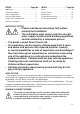
LIMITS OF APPLICATION Part No Model Supply Max. Liquid Temp. o C Min. Max. Liquid Ambient Temp. Air Temp o o C C Max. Suction Lift (m) Max. Head (Pump Closed Valve) (m) 50 Hz 60 Hz Max. Viscosity (Redwood No. 1 Scale) Centistokes **Max. Max. Inlet Head (m) Working Max. No. Pressure Starts/h kPa (bar) 50 Hz 60 Hz 46628 PH 45 TS S 230/1/50 80 4 40 4.6* 40 50 9.5 600 (6) 21 60 46629 PH 45 TS S 230/1/50 80 4 40 4.6* 40 50 9.5 600 (6) 21 60 * With footvalve fitted.
Do not allow plastic pump parts to come into contact with oil or cellulose based paints, paint thinners or strippers, acid based descalents or aggressive cleaning agents. Do not introduce solder flux to pumps or pump parts manufactured from plastic. All solder joints should be completed and flux residues removed prior to pump connection. Always install isolating valves to both suction and delivery pipework. The motor casing can become very hot under normal operating conditions.
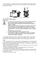
When a footvalve is installed on installations that incorporate automatic pump control, it is recommended that a suitable pressure relief valve be fitted in the discharge (outlet) pipework from the pump. INLET Fig. 1 OUTLET PH 45 TS S ELECTRICAL INSTALLATION WARNINGS: The electrical installation must be carried out in accordance with the current national electrical regulations by a competent person. Before starting work on the electrical installation ensure the power supply is isolated.
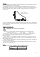
Earthing This appliance must be earthed via the supply cord, which must be correctly connected to the earth point located in the terminal box. Metallic pipework must have supplementary earth bonding where the continuity has been broken by flexible hoses or plastic components. Adjacent suction and delivery pipes should be fitted with earthing clamps to BS 951 and connected with earthing wire size 4 mm² (Fig. 2). Diagram of earth continuity connection. Fig.
Supply Cord Replacement: The supply cord and internal wiring within the terminal box are routed and secured to ensure compliance with the electrical standard EN 60335-1. It is essential that prior to any disturbance of this internal wiring, all cable routing and securing details are carefully noted to ensure re-assembly to the same factory pattern is always maintained.
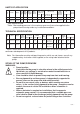
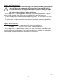
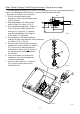
Cable Gland & Supply Cord Fitting Instructions (Single phase range) The cable gland assembly Fig. 5 (items 1 & 2) provides the necessary protection against ingress of solid objects and moisture as well as providing cable retention. Assembly instructions are as follows: 80 1. Ensure selected cable sheath 8 diameter is within the permitted range N (6.5 to 9.5 mm). E 2. Strip and prepare the cable sheath L (Dims. in mm) and insulators as shown in Fig. 3. 12 8 3. Disassemble cable gland as shown in 70 Fig.
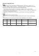
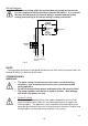
Wiring Diagrams The internal wiring within the terminal box are routed and secured to ensure compliance with the electrical standard EN 60335-1. It is essential that any disturbance of this internal wiring is avoided and the factory routing and securing of all internal wiring is always maintained. RED MAIN WINDING BLACK CAPACITOR BLUE BROWN THERMO TRIP START WINDING TERMINAL BLOCK GREEN / YELLOW N BLUE BROWN L L N E 230 VAC/1PH/50Hz SUPPLY Fig.
2. Liquid Supply Always ensure that liquid storage capacity is adequate to meet the demand. Ensure the pump chamber is full of liquid before starting the pump. Failure to do this could result in seal damage. To ensure dry running does not occur the pumps must be primed as described in the priming section. Do not run pump dry. 3. Ensure electrical supply is compatible with the details that are stated on the pump rating plate. (The wrong voltage or frequency can be dangerous and may damage the pump.) 4.
MAINTENANCE WARNINGS: Care should be taken to protect the pump from frost and freezing. Pump Location If possible site the pump in a location where in the unlikely event of a liquid leak, any spillage is contained or routed to avoid electrics or areas sensitive to water damage. 1. No routine maintenance is required but provision should be made for easy access to the pump to allow for repairs due to normal wear and tear. 2. Disconnect electrical supply before working on pump. 3.
TROUBLE SHOOTING GUIDE Symptoms Probable Cause Recommended Action Pump will not start. Electrical supply. Check power to motor. Check the circuit breaker is set. Check the correct fuse is being used. Starter thermal overload tripped. Check overload in starter (if applicable). Investigate cause of problem. Internal motor thermotrip activated. Wait for thermotrip to cool and autoreset. Investigate cause of problem. Air locked. Bleed pipework and pump to clear air. No liquid supply.
YOUR 1 YEAR GUARANTEE Stuart Pumps are guaranteed by Stuart Turner Limited to be free from defects in materials or workmanship for the applicable guarantee period from the date of purchase. The applicable guarantee period is stated in the installation booklet supplied with the pump. Within the guarantee period we will repair, free of charge, any defects in the pump resulting from faults in material or workmanship, repairing, exchanging parts or exchanging the whole unit as we may reasonably decide.
NOTES - 15 -
DECLARATION OF CONFORMITY 2006/42/EC BS EN ISO 12100-1, BS EN ISO 12100-2, BS EN 809 2006/95/EC BS EN 60335-1, BS EN 60335-2-41 2004/108/EC BS EN 55014-1, BS EN 55014-2, BS EN 55022, BS EN 61000-3-2, BS EN 61000-3-3, BS EN 61000-4-2, BS EN 61000-4-3, BS EN 61000-4-4, BS EN 61000-4-5, BS EN 61000-4-6, BS EN 61000-4-11 1999/519/EC BS EN 62233 2011/65/EU IT IS HEREBY CERTIFIED THAT THE STUART ELECTRIC MOTOR DRIVEN PUMP AS SERIAL NUMBER BELOW, COMPLIES WITH THE ESSENTIAL REQUIREMENTS OF THE ABOVE E.E.C.