Installation, Operation & Maintenance Instructions Please leave this instruction booklet with the home owner as it contains important guarantee, maintenance and safety information Read this manual carefully before commencing installation. This manual covers the following products: Monsoon U2.0 bar Single Monsoon U4.5 bar Single Pt. No. 46498 Pt. No. 46414 Monsoon U3.0 bar Single Pt. No.
PRODUCT DESCRIPTION Electric motor driven peripheral pump complete with an automatic control system, consisting of flow switch, pressure switch, pressure vessel and electronic control. APPLICATION The Universal Single pumps are suitable for positive or negative head installation conditions. The pumps are designed for pressure boosting applications in vented stored, hot or cold, clean water systems, where under gravity, no flow is available.
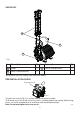
CHECKLIST B C A Fig. 1 Item Description Qty Item Description A Pump 1 B Hose & sealing washer 2 C Tank & sealing washer Qty 1 Your product may vary slightly from the picture above. PRE-INSTALLATION CHECK Pressure vessel Fig. 2 The pressure vessel (Fig. 2) is factory fitted to the pump assembly. To eliminate any risk that the vessel has lost its assembly torque and sealing ability during transit, it must be checked prior to installation and should be hand tight. Cont ...
1 READ BEFORE COMMENCING PUMP INSTALLATION A. Water storage capacity. 1.11 The hot and cold water storage capacity must be sufficient to meet the flow rates required by the pumped equipment and any other water using fittings and appliances, which may be operated simultaneously. 1.12 Ensure the pump is primed as described in the priming section before starting, damage to the shaft seal will result otherwise. See Section 5 - Commissioning. B.
2 LOCATION - GENERAL 2.16 2.17 2.18 2.19 2.20 2.21 2.22 2.23 2.24 2.11 Access: For emergencies and maintenance the pump must be easily accessible. 2.12 Protection: The pump must be located in a dry position, frost free and protected from freezing, particularly when installed in a loft (not recommended). 2.13 Ventilation: Ensure an adequate air flow to cool the pump. Separate the pump from other appliances that generate heat. An 80 mm (3 “) air gap must be maintained around the pump. 2.
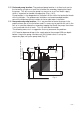
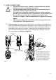
Max. outlet head 12 m (8 m U2.0 bar) 350 mm min Least preferred area Negative head 200 mm min Max. inlet head 12 m (8 m U2.0 bar) Min. inlet head 0.5 m 2.25 Preferred pump location: The preferred pump location is at floor level next to the hot water cylinder or a level that is below the secondary tapping that feeds the pump. This will ensure the pump has access to an air free water supply which is important for trouble free operation (Figs. 4 & 5).
2 LOCATION - COLD WATER Fig. 4 Static Outlet Pressure (see table 1) Static Inlet Pressure (see table 1) Table 1 Model U2.0 bar Single Min. static inlet head (m) Max. static inlet head (m) Max. static outlet head (m) 0.5 8 8 0.5 12 12 U3.0 bar Single U4.5 bar Single 2.
Hot water connection: (Applicable to U2.0 and U3.0 bar Singles) 2.29 Hot water cylinder or storage tank: When a hot water cylinder or storage tank is used, ensure the pipework size from the cold water storage to the hot water storage is of adequate size and a minimum of 22 mm. The U4.5 bar Single should have pipework of a minimum of 28 mm. 2.30 Hot water supply: The pump must be supplied with a dedicated feed direct from the hot water cylinder or storage tank.
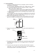
3 PUMP CONNECTIONS Do not use stainless steel, chrome or nickel plated pipe with the flexible hose push-in plumbing connections. Do not introduce solder flux into the joint or surrounding area as connectors will be attacked and may fail. All solder joints should be completed and flux residues removed before final connection to push-in connections, on the flexible hose.
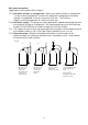
3.12 Hose to pipework: 1. The hoses are fitted with plastic push-in connectors, which must only be connected with the following: a) 22 mm diameter copper pipe to BS EN 1057 - R250 (half hard) - Table 3. b) 22 mm plastic pipe to BS 7291 part 1 and part 2 (Table 1), or part 3 (Table 1) plus internal support sleeve*. * The internal bore of the plastic pipe must be supported against collapse with the pipe manufacturers recommended support sleeve (pipe insert).
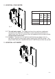
3.13 Typical Low Level Installation: In certain installations it may be necessary to install a 90° bend on the inlet or outlet connections of the pump before the flexible hose to accommodate a low level installation. Below are some preferred connection options. All connections seal on the pump body using a fibre or rubber sealing washer. Tap connector fittings should be used which must be of an appropriate pressure and temperature rating.
4 ELECTRICAL INSTALLATION 4.11 Regulations: The electrical installation must be carried out in accordance with the current national electrical regulations and installed by a qualified person. 4.12 Safety: In the interests of electrical safety a 30 mA residual current device (R.C.D. not supplied) should be installed in the supply circuit. This may be part of a consumer unit or a separate unit. 4.13 Before starting work on the electrical supply ensure power supply is isolated. 4.
The wire which is coloured blue must be connected to the terminal which is marked with the letter N or coloured black. The wire which is coloured brown must be connected to the terminal which is marked with the letter L or coloured red. 4.21 Wiring Diagram: BLUE START WINDING N A M N L S1 S2 S3 S3 S2 S1 CAPACITOR BLACK THERMOTRIP BROWN LINK WIRE (BLUE) MAIN WINDING BLUE BROWN GREEN / YELLOW N 230 VAC/1PH/50Hz L SUPPLY E FLOWSWITCH REED (S3) PRESSURE SWITCH (S1) Fig. 12 4.
4.24 Cable Gland Fitting Instructions: 1 2 Fig. 13 To enable correct assembly of the cable gland the ‘O’-ring (Fig. 13 item 1) must be placed over the cable before the clamping insert (Fig. 13 item 2) can be tightened. Note: Cable diameter range:- 6.5 mm to 9.5 mm. 4.25 Supply Cord Extension: The pumps are fitted with a supply cord to the following specification:All models . . . . . . . . . . . . . . . . . HO5VV-F3 G 0.75 mm² - 6 Amp rated cable.
5 COMMISSIONING 5.11 System Flushing: This pump incorporates push-in connectors and plastic components that must not come into contact with solder flux, acid-based descalents or aggressive cleaning agents. The pipework system should be flushed out prior to the pump being connected to ensure any contaminants/chemical residues and foreign bodies are removed from elsewhere in the system. 5.12 Water Supply: Always ensure that water storage capacity is adequate to meet the demand.
5.14 Starting: a) Ensure all outlets are closed, turn power supply ‘on’ - pump will start, pressurise the system then stop. b) Open and close all outlets in turn associated with the pump, (including w/c systems) allowing water to flow from each outlet until all air is purged. As each outlet is opened and closed, the pump will start and stop respectively. Note: After closing the outlet there will be a small delay time before the pump stops, which is normal.
6 MAINTENANCE 6.11 Turn off water supplies to the pump and release pressure by opening water outlets before attempting maintenance. 6.12 Inlet strainer: The inlet strainers may require periodical cleaning. The frequency of this operation is dependent upon installation conditions. The strainer is located in the inlet assembly of the pump casing (Fig. 15) and is removed as follows:a) Isolate pump electrically. b) Release all system pressure.
6.14 Should ever the need arise for the vessel to have its air charge checked or replenished, it should be carried out as follows: a) Isolate pump electrically. b) Isolate hot and cold water supplies via the integral pump isolating valve located in the flexible hoses (see Section 3 - Pump Connections). c) Release system water pressure by opening a system outlet (tap). d) Check air charge at Schrader valve (Fig. 16) using a tyre pressure gauge. Vessel Pressure Model U2.0 bar Single U3.0 bar Single U4.
7 TECHNICAL SPECIFICATION Dimensions Mechanical Electrical Model U2.0 Single U3.0 Single U4.5 Single Power supply Volts/phase freqency 230/1/50 230/1/50 230/1/50 Enclosure IPX4 IPX4 IPX4 Type of motor Induction Induction Induction Power consumption 250 Watts 390 Watts 555 Watts Full load current 1.1 Amps 1.7 Amps 2.5 Amps Rating Continuous (S1) @ 9 l/min & above Continuous (S1) @ 9 l/min & above Continuous (S1) @ 9 l/min & above Max.
8 TROUBLE SHOOTING GUIDE Symptoms Probable Cause Recommended Action Pump will not start. Electrical supply. Check power supply. Check fuse (see fuse section). Check circuit breaker is set. Check wiring connections. Pump Jammed. If motor ‘Buzzes’ switch off power and contact Stuart Turner. Damaged pressure switch. Turn off power. Release system water pressure. Turn on power, pump should start. If NOT contact Stuart Turner. Recommended static inlet/outlet heads exceeded.
8.11 Dry Run Protection: This pump is fitted with a PCB that will detect the following fault conditions: Dry running caused by water starvation to the pump. Should the pump run out of water it will stop as part of a “protective logic sequence”. The fault should be rectified before re-starting the pump. Check that there is sufficient water supply to the pump and also ensure that all terminal fitting outlets are closed. 8.
IMPORTANT – Ensure there is no contact with any of the internal parts of the terminal box. Briefly reconnect the mains power supply to the pump – the indicator light should illuminate if the pump has been correctly wired. Isolate the mains electrical power supply from the pump. Re fit the terminal box lid ensuring no cables are trapped. Re fit the four terminal box lid retaining screws, tighten to 0.8 Nm. Indication light Terminal box lid Retaining screws x 4 Fig.
8.14 Flow Switch Circuit Test: 1. First confirm visually that the flow switch reed clamps have not been dislodged during handling or installation. The clamps must be fully located within their flow switch body groove as shown. 2. To carry out the following test you will need to obtain a magnet, a typical fridge magnet is suitable. 3. Ensure the power supply is switched on. 4. Position the magnet directly in front of the reed clamp as shown.
9 THE MONSOON GUARANTEE Congratulations on purchasing a Stuart Turner pump. We are confident this pump will provide many years of trouble free service as all our products are manufactured to the very highest standard. All Monsoon Pumps are guaranteed to be free from defects in materials or workmanship for 3 years from the date of purchase.
In the event of a claim please telephone ‘Pump Assist’ or return the pump and flexible hoses with the accessories removed e.g pipes etc. If you have any doubt about removing a pump, please consult a professional. 0844 98 000 97 Proof of purchase should accompany the returned unit to avoid delay in investigation and dealing with your claim. You should obtain appropriate insurance cover for any loss or damage which is not covered by Stuart Turner Ltd in this provision. Please record here for your records.
NOTES - 26 -
NOTES - 27 -
DECLARATION OF CONFORMITY 2006/42/EC BS EN ISO 12100-1, BS EN ISO 12100-2, BS EN 809 2006/95/EC BS EN 60335-1, BS EN 60335-2-41 2004/108/EC BS EN 55014-1, BS EN 55014-2, BS EN 55022, BS EN 61000-3-2, BS EN 61000-3-3, BS EN 61000-4-2, BS EN 61000-4-3, BS EN 61000-4-4, BS EN 61000-4-5, BS EN 61000-4-6, BS EN 61000-4-11 1999/519/EC BS EN 62233 2011/65/EU IT IS HEREBY CERTIFIED THAT THE STUART ELECTRIC MOTOR DRIVEN PUMP AS SERIAL NUMBER BELOW, COMPLIES WITH THE ESSENTIAL REQUIREMENTS OF THE ABOVE E.E.C.