Installation, Operation & Maintenance Instructions Please leave this instruction booklet with the owner as it contains important guarantee, maintenance and safety information Read this manual carefully before commencing installation. This manual covers the following products: Monsoon Extra 2.6 bar PS Monsoon Extra 3.6 bar PS Pt. No. 46601 Pt. No.
PRODUCT DESCRIPTION Electric motor driven centrifugal pump complete with an automatic control system, consisting of flow switch, pressure switch, pressure vessel and electronic control. APPLICATION The Monsoon Extra Pressure Set (PS) range is designed for pressure boosting applications in vented stored, cold clean water systems, where under gravity, no flow is available and can be used in systems where a negative head exists.
CHECKLIST 28 mm copper outlet pipework (discharge). Short 28 mm copper pipe tails to connect between isolating valve and flexible pipes. 28 mm flexible pipes. These hoses are fitted with G 1 female connector suitable for connection to a G 1 (1 “ BSP) adaptor or fitting. IMPORTANT: With the pump removed from its packaging check for any damage prior to installation. If any damage is found contact Stuart Turner Ltd within 24 hours of receipt.
1 READ BEFORE COMMENCING PUMP INSTALLATION A. Water storage capacity. 1.11 The cold water storage capacity must be sufficient to meet the flow rates required by the pumped equipment and any other water using fittings and appliances, which may be operated simultaneously. 1.12 Ensure the pump is primed as described in the priming section before starting, damage to the shaft seal will result otherwise. See Section 5 - Commissioning. B.
2 LOCATION - GENERAL 2.16 2.17 2.18 2.19 2.20 2.21 2.22 2.23 2.24 2.25 2.11 Access: For emergencies and maintenance the pump must be easily accessible. 2.12 Protection: The pump must be located in a dry position, frost free and protected from freezing, particularly when installed in a loft (not recommended). 2.13 Ventilation: Ensure an adequate air flow to cool the pump. Separate the pump from other appliances that generate heat. An 80 mm (3 “) air gap must be maintained around the pump. 2.
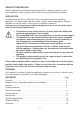
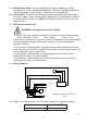
2 LOCATION Static outlet pressure Max. 13 m Static inlet pressure Min. 1 m Max. 10 m Unvented hot water cylinder Cold water Hot water Fig. 2 2.26 The cold water supply: The supply must be AIR FREE and have a DEDICATED CONNECTION to the tank which should be via a tank connector, positioned at a slightly lower level (25 mm minimum) than the feed pipe to the hot water cylinder. Do not connect to the mains. 2.
3 PUMP CONNECTIONS 3.11 Hose to pump: These pumps have G 1 threaded connections to accept the hoses supplied. The hose end is made water tight with a sealing washer on assembly, nip tight to 4/5 Nm for water tight seal (Do not overtighten). 3.12 Hose to pipework: Hoses terminating in G 1 threaded connections are supplied and when securing the male end to a suitable pipe fitting, seal with PTFE tape or other suitable sealant. Cont ...
4 ELECTRICAL INSTALLATION / EARTHING 4.11 Regulations: The electrical installation must be carried out in accordance with the current national electrical regulations and installed by a qualified person. 4.12 Safety: In the interests of electrical safety a 30 mA residual current device (R.C.D. not supplied) should be installed in the supply circuit. This may be part of a consumer unit or a separate unit. 4.13 Before starting work on the electrical supply ensure power supply is isolated. 4.
4.19 Additional earthing: Certain installations may require additional earthing arrangements such as equipotential bonding. Reference should be made to the relevant regulations concerning this subject to ensure compliance. 4.20 Connections: The pump must be permanently connected to the fixed wiring of the mains supply using the factory fitted supply cord, via a double pole switched fused spur off the ring main and NOT connected to the boiler or the immersion heater circuits. 4.
4.24 Supply Cord Replacement: The supply cord and internal wiring within the terminal box are routed and secured to ensure compliance with the electrical standard EN 60335-1. It is essential that prior to any disturbance of this internal wiring, all cable routing and securing details are carefully noted to ensure re-assembly to the same factory pattern is always maintained.
5 COMMISSIONING / SYSTEM FLUSHING/ PRIMING / STARTING 5.11 System Flushing The pipework system should be flushed out prior to the pump being connected to ensure any contaminants/chemical residues and foreign bodies are removed from elsewhere in the system. 5.12 Water Supply: Always ensure that water storage capacity is adequate to meet the demand. Ensure the pump chamber is full of water before starting the pump. Failure to do this could result in seal damage.
6 MAINTENANCE 6.11 Turn off water supplies to the pump and release pressure by opening water outlets before attempting maintenance. 6.12 Inlet strainer: Incorporated in the strainer is a removable gauze filter which may require periodic cleaning. The frequency of this operation is dependent upon installation conditions. The strainer is located in the inlet pipework to the pump (Fig. 8). The gauze filter is removed as follows:a) Isolate pump electrically. b) Release all system pressure.
Model Schrader valve (under cap) All other models Air Charge bar (psi) 2.1 (30) Cap Pressure vessel Fig. 9 6.14 Water scale: As water is heated scale deposits are released in areas of hard water, scale can cause the mechanical seal to stick if left without use for long periods. The pump must be run for at least 5 minutes every four weeks to “exercise” all working parts. Run on cool water. See Section 7 - Technical Specification for note on water temperature.
7 TECHNICAL SPECIFICATION Pump Dimensions Mechanical Electrical Model 2.6 bar PS 3.6 bar PS Power supply Volts/phase frequency 230/1/50 230/1/50 Enclosure IPX5 IPX5 Type of motor Induction Induction Power consumption 775 Watts 1136 Watts Full load current 3.5 Amps 5.1 Amps Rating Continuous (S1) Continuous (S1) Max.
8 TROUBLE SHOOTING GUIDE Symptoms Probable Cause Recommended Action Pump will not start. Electrical supply. Check power supply. Check fuse (see fuse section). Check circuit breaker is set. Check wiring connections. Pump Jammed. If motor ‘Buzzes’ switch off power and contact Stuart Turner. Damaged pressure switch. Turn off power. Release system water pressure. Turn on power, pump should start. If NOT contact Stuart Turner. Recommended static inlet/outlet heads exceeded.
8.11 Dry Run Protection: This pump is fitted with a safety control circuit, which will detect the following fault condition: Dry running caused by water starvation to the pump. Should the pump run out of water it will stop as part of a “protective logic sequence”, detailed below. The fault should be rectified before re-starting the pump. Check that there is sufficient water supply to the pump and also ensure that all terminal fitting outlets are closed. 8.
Briefly reconnect the mains power supply to the pump – the ‘power on’ light should illuminate if the pump has been correctly wired. Isolate the mains electrical power supply from the pump. Re fit the terminal box lid ensuring no cables are trapped. Re fit the four terminal box lid retaining screws, tighten to 0.8 Nm. Terminal box lid Retaining screws x 4 ‘Power on’ light Fig. 10 Wiring removed for clarity 8.
9 THE MONSOON EXTRA GUARANTEE Congratulations on purchasing a Stuart Turner pump. We are confident this pump will provide many years of trouble free service as all our products are manufactured to the very highest standard. All Monsoon Extra pumps are guaranteed to be free from defects in materials or workmanship for 2 years from the date of purchase.
Proof of purchase should accompany the returned unit to avoid delay in investigation and dealing with your claim. You should obtain appropriate insurance cover for any loss or damage which is not covered by Stuart Turner Ltd in this provision. Please record here for your records. TYPE NO. SERIAL NO.
DECLARATION OF CONFORMITY 2006/42/EC BS EN ISO 12100-1, BS EN ISO 12100-2, BS EN 809 2006/95/EC BS EN 60335-1, BS EN 60335-2-41 2004/108/EC BS EN 55014-1, BS EN 55014-2, BS EN 55022, BS EN 61000-3-2, BS EN 61000-3-3, BS EN 61000-4-2, BS EN 61000-4-3, BS EN 61000-4-4, BS EN 61000-4-5, BS EN 61000-4-6, BS EN 61000-4-11 1999/519/EC BS EN 62233 2011/65/EU IT IS HEREBY CERTIFIED THAT THE STUART ELECTRIC MOTOR DRIVEN PUMP AS SERIAL NUMBER BELOW, COMPLIES WITH THE ESSENTIAL REQUIREMENTS OF THE ABOVE E.E.C.