
Instruction Manual


- 5 -
Cont ...
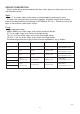
PUMP CONNECTIONS
Model Inlet
(Pump)
Outlet Fig. No.
4000 G 1 Female G 1 Female 2
6000 G 1 Female G 1 Female 2
K7-2 G 1 Female G 1 Female 4
L5-4S G 1¼ Female G 1 Female 3
L7-4S G 1¼ Female G 1 Female 3
T6-2 G 1 Female G 1 Female 1
T12-2 G 1 Female G 1 Female 1
PUMPS
PUMPS
PUMPS
Fig. 1
Reed Switch
Assembly
Reed Switch
Assembly
Reed Switch
Assembly
Reed Switch
Assembly
Inlet
Inlet
Inlet
Inlet
Outlet
Outlet
Outlet
Outlet
Fig. 2
Fig. 4
Fig. 3