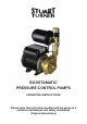
BOOSTAMATIC PRESSURE CONTROL PUMPS OPERATING INSTRUCTIONS Please leave this instruction booklet with the pump as it contains maintenance and safety information (Original Instructions)
PRESSURE CONTROL MODELS Boostamatic 4000 Boostamatic 6000 Boostamatic K7-2 Boostamatic L5-4S Boostamatic L7-4S Boostamatic T6-2 Boostamatic T12-2 INDEX . . . . . . . . . . . . . . . . . . . . . . . . . . . . . . . . . . . . . . . . . . . . . . . . . . Page No Application . . . . . . . . . . . . . . . . . . . . . . . . . . . . . . . . . . . . . . . . . . . . . . . . . . . . . . . . . . . . . . . . . . . 2 Product Description . . . . . . . . . . . . . . . . . . . . . . . . . . . . . . . . . . . . . . . .
PRODUCT DESCRIPTION Electric motor driven pump complete with flow switch, pressure switch, pressure vessel and electronic control. Motor Class ‘F’ insulation, totally enclosed fan ventilated cooling, continuously rated. All motors are induction type, permanent capacitor, fitted with integral auto resetting thermal overload protection and comply with BS5000 or IEC 34-1. Enclosure ratings are given in the technical specification section. Pump Close coupled to motor.
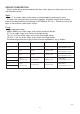
LIMITS OF APPLICATION Supply (Note ****) Max. Liquid Temp. o C (Note ***) Min. Liquid Temp. o C Max. Suction Lift (m) (Note *) 4000 230/1/50 65 4 4.6 60 1.4 6000 230/1/50 65 4 4.6 60 K7-2 230/1/50 65 4 4.6 L5-4S 230/1/50 65 4 L7-4S 230/1/50 65 T6-2 230/1/50 T12-2 230/1/50 Model Max. No. Cut in Cut Out Starts/h Pressure Flow (bar) (l/min) Max. Working Pressure kPa (bar) (Note **) Max. Inlet Head (m) Max. Head (m) (pump closed valve) 1.0 600 (6) 13 29.5 1.4 1.
PUMP CONNECTIONS Reed Switch Assembly Outlet Reed Switch Assembly Outlet PUMPS Inlet Inlet Fig. 1 Fig. 2 Outlet Reed Switch Assembly Outlet Reed Switch Assembly Inlet PUMPS Inlet Fig. 3 Model Fig. 4 Inlet (Pump) Outlet Fig. No. 4000 G 1 Female G 1 Female 2 6000 G 1 Female G 1 Female 2 K7-2 G 1 Female G 1 Female 4 L5-4S G 1¼ Female G 1 Female 3 L7-4S G 1¼ Female G 1 Female 3 T6-2 G 1 Female G 1 Female 1 T12-2 G 1 Female G 1 Female 1 Cont ...
PRE-INSTALLATION ASSEMBLY Pressure Check and Assembly of Pressure Vessel a) Certain models are supplied in two parts, the main pump and the pressure vessel. The pressure vessel is pre-charged with air at the factory (see table below). This pressure should be checked at the Schrader valve (Fig. 5) using a tyre pressure gauge and adjusted if necessary using a car or bicycle pump prior to installation. b) To assemble the vessel (when applicable), remove protective plastic cap from fitting point.
Re-positioning of Pressure Vessel The pressure vessel can be rotated to alternative positions (Figs. 7, 8 & 9) in the event of the factory fitted position being unsuitable for a specific installation. a) Remove pressure vessel by unscrewing anti-clockwise. b) Using a 2 mm allen key, carefully loosen all three retaining grub screws by two turns (Fig. 6). c) Warning - Care must be taken when re-positioning the pressure vessel to ensure no strain is placed upon the pressure switch or reed switch cables.
SITING OF THE PUMP/PIPEWORK WARNINGS: Pump Location If possible site the pump in a location where in the unlikely event of a liquid leak, any spillage is contained or routed to avoid electrics or areas sensitive to liquid damage. Care should be taken to protect pump from frost and freezing. Ensure pipework to and from pump is independently supported to prevent forces being transferred to inlet and outlet branches of pump.
Outlet Flow must be in direction of flow switch arrow (vertically upwards) Fig. 10 To prevent loss of pressure through pipework, use pipe size to match pump whenever possible, minimising 90° bends. It must be ensured that storage capacity of the liquid supply is adequate for the flow rates required by the pump. The pipework feeds to the storage tank should be of adequate size to ensure replenishment rate of tanks is sufficient to meet the needs of the pump.
Diagram showing typical Pressure Control installation with suction lift. Max. outlet head 8 m (K7-2 only) Max. inlet head (consult limits of application section) Max. outlet head 13 m (except K7-2) Pump Mounted Above Liquid Source (Suction Lift Installation) Fig.
ELECTRICAL INSTALLATION WARNINGS: The electrical installation must be carried out in accordance with the current national electrical regulations and installed by a competent person. In the interests of electrical safety a 30 mA residual current device (R.C.D.) should be installed in the supply circuit. This may be part of a consumer unit or a separate unit. Before starting work on the electrical installation ensure the power supply is isolated. This appliance must be earthed.
Wiring The Wires in the mains lead (supply cord) are coloured in accordance with the following code: Green and Yellow: Earth Blue: Neutral Brown: Live As colours of the core in the new mains lead may not correspond with the coloured markings identifying the terminals in your connection unit, proceed as follows: The wire which is coloured Green and yellow must be connected to the terminal marked with the letter ‘E’ or by the earth symbol or coloured green or green and yellow.
Supply Cord Replacement If the supply cord needs to be replaced, cord selection should be chosen in accordance with the current involved, surrounding conditions and recommended fuse size. For information on cable fitting and connection, consult the wiring diagram and cable gland fitting instructions. Cable Gland Fitting Instructions (Motor Terminal Box) 1 2 2 1 L5-4S, L7-4S T6-2, T12-2 Fig. 16 4000, 6000, K7-2 To enable correct assembly of the cable gland, the ‘O’-ring (Fig.
1. System Flushing This pump-set incorporates plastic components that must not come into contact with solder flux, acid-based descalents or aggressive cleaning agents. The pipework system should be flushed out prior to the pump being connected to ensure any contaminants/chemical residues and foreign bodies are removed from elsewhere in the system. 2. Liquid Supply Always ensure that liquid storage capacity is adequate to meet the demand. Ensure the pump chamber is full of liquid before starting the pump.
5. Starting The Pump a) Ensure all outlets are closed, turn power supply ‘on’ - pump will start, pressurise the system then stop. b) Open and close all outlets in turn associated with the pump, allowing liquid to flow from each outlet until all air is purged. As each outlet is opened and closed, the pump will start and stop respectively. Note: After closing the outlet there will be a small delay time before the pump stops, which is normal.
5. As water is heated scale deposits are released in areas of hard water (usually south of a line between the Wash and Bristol Channel), scale can cause the mechanical seal to stick if left without use for long periods. We recommend the pump is run for at least 5 minutes every four weeks to “exercise” all working parts. Run on cool water. 6. After maintenance is completed, refer to the starting and commissioning sections for instructions on re-starting pump.
TROUBLE SHOOTING GUIDE Symptoms Probable Cause Recommended Action Pump will not start. Electrical supply. Check wiring connections. Check all switches are ‘on’. Check fuse (see fuse section). Check circuit breaker is set. Faulty reed switch/PCB. Refer to circuit test as detailed in Fig. 21. Recommended static inlet/outlet heads exceeded. Re-position pump (see pump location section). Internal motor thermotrip activated.
Dry Run Protection This pump is fitted with a safety control circuit, which will detect the following fault condition: Dry running caused by water starvation to the pump. Should the pump run out of water it will stop as part of a “protective logic sequence”, detailed below. The fault should be rectified before re-starting the pump. Check that there is sufficient water supply to the pump and also ensure that all terminal fitting outlets are closed.
ENVIRONMENT PROTECTION Your appliance contains valuable materials which can be recovered or recycled. At the end of the products’ useful life, please leave it at an appropriate local civic waste collection point. YOUR 1 YEAR GUARANTEE Stuart Pumps are guaranteed by Stuart Turner Limited to be free from defects in materials or workmanship for the applicable guarantee period from the date of purchase. The applicable guarantee period is stated in the installation booklet supplied with the pump.
DECLARATION OF CONFORMITY 2006/42/EC BS EN ISO 12100-1, BS EN ISO 12100-2, BS EN 809 2006/95/EC BS EN 60335-1, BS EN 60335-2-41, EN 50366 2004/108/EC BS EN 55014-1, BS EN 55014-2, BS EN 55022, BS EN 61000-3-2, BS EN 61000-3-3, BS EN 61000-4-2, BS EN 61000-4-3, BS EN 61000-4-4, BS EN 61000-4-5, BS EN 61000-4-6, BS EN 61000-4-11 IT IS HEREBY CERTIFIED THAT THE STUART ELECTRIC MOTOR DRIVEN PUMP AS SERIAL NUMBER BELOW, COMPLIES WITH THE ESSENTIAL REQUIREMENTS OF THE ABOVE E.E.C. DIRECTIVES.