
User's Manual
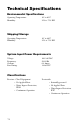
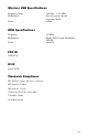
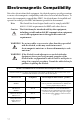
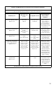


Table Of Contents
- Table of Contents
- Warnings and Cautions
- 1. Read this operating manual thoroughly and be familiar with its contents prior to using this equipment.
- 2. Carefully unpack the unit and check if any damage occurred during shipment. If damage is detected, please refer to the Service section in this manual.
- 3. Avoid removing covers on the unit and attempting internal repairs or adjustments not specifically detailed in this operating manual.
- 4. Pay close attention to the care and cleaning instructions in this manual. A deviation may cause damage to the device.
- 5. Never sterilize the Wireless Universal footswitch components.
- 6. Be completely familiar and comfortable with the operation of the Wireless Universal footswitch. Training may be required before some operators are thoroughly familiar with how to properly operate the footswitch.
- 7. When the Receiver is interconnected with other medical electrical equipment, leakage currents may be additive. Ensure all systems are installed according to the requirements of IEC 60601-1-1.
- Symbol Definitions
- Product Description and Intended Use
- 1. A wireless footswitch, which provides pedals similar to those found on other footswitches and transmits radio signals to a radio receiver console
- 2. A radio receiver console, which routes commands from the footswitch to devices that connect to the receiver’s rear panel.
- The Footswitch
- The Receiver
- Front Panel
- 1. Power Switch: Powers on and off the receiver. The switch will illuminate when the unit is on.
- 2. Synchronize port 1: Enables a footswitch to work with the receiver when aligned with the synchronize logo on that footswitch. The footswitch will be designated as “footswitch 1.”
- 3. Mode button 1: Selects which device footswitch 1 will control (which “mode” the footswitch is in). Pressing and holding this button will clear the Footswitch.
- 4. Active-device display 1: Displays which device is currently active and can be controlled by footswitch 1 (which “mode” footswitch 1 is in).
- 5. Active-device display 2: Displays which device is currently active and can be controlled by footswitch 2 (which “mode” footswitch 2 is in).
- 6. Mode button 2: Selects which device footswitch 2 will control (which “mode” the footswitch is in). Pressing and holding this button will clear the Footswitch
- 7. Synchronize port 2: Enables a second footswitch to work with the receiver when aligned with the synchronize logo on that footswitch. The footswitch will be designated as “footswitch 2.”
- Rear Panel
- 1. TPS output: Provides a dedicated connection to the TPS console, enabling the commands issued from the footswitch to be routed to the TPS console.
- 2. SERFAS output: Provides a dedicated connection to the SERFAS console, enabling the commands issued from the footswitch to be routed to the SERFAS console.
- 3. Expansion port: Provides a generic connection to addition devices, enabling the commands issued from the footswitch to be routed to the console.
- 4. Expansion port: Provides a generic connection to addition devices, enabling the commands issued from the footswitch to be routed to the console.
- 5. SFB Serial Connectors: Enables firewire connection with newer devices, such as CORE and SERFAS Energy, eliminating the need for multiple connection cables.
- 6. Volume control: Controls the output volume.
- 7. AC-power input: Connects to the AC Power cord, which connects to a hospital-grade power outlet.
- Setting up the iSwitch
- footswitch Receiver
- Reverse
- Cut
- Using the Receiver Controls
- Cleaning and Maintenance
- Troubleshooting
- Technical Specifications
- Electromagnetic Compatibility
- Warranty
- Service and Claims
- 1. Contact Stryker Endoscopy at 1-800-624-4422, or phone your local Stryker Endoscopy sales representative.
- 2. Clean and sterilize all parts that will be returned for service. Follow the instructions provided in this manual.
- 3. Package all the components carefully in the original shipping container if possible.
- 4. Ship the unit, pre-paid and insured to:
- Other Service
20
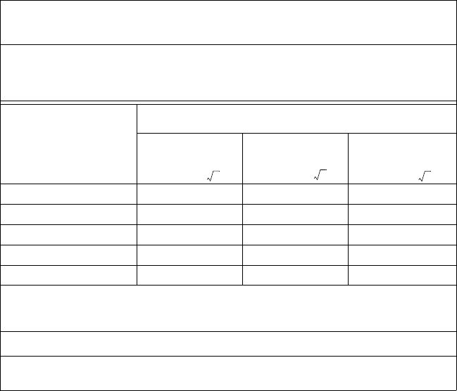
Recommended Separation Distances Between Portable and Mobile RF Communications
Equipment and the iSwitch System
The iSwitch system is intended for use in an electromagnetic environment in which radiated RF disturbances are
controlled. The user of the iSwitch system can help prevent electromagnetic interference by maintaining a mini
-
mum distance between portable and mobile RF communications equipment (transmitters) and the iSwitch sys-
tem as recommended below, according to the maximum output power of the communications equipment.
Rated maximum output
power (W) of transmitter
Separation distance (m) according to frequency of transmitter
150 kHz to 80
MHz
80 MHz to 800
MHz
800 MHz to 2.5
GHz
0.01 0.12 0.12 0.23
0.1 0.37 0.37 0.74
1 1.17 1.17 2.33
10 3.70 3.70 7.37
100 11.70 11.70 23.30
For transmitters rated at a maximum output power not listed above, the recommended separation distance (d) in
meters (m) can be estimated using the equation applicable to the frequency of the transmitter, where P is the
maximum output power rating of the transmitter in watts (W) according to the transmitter manufacturer.
NOTE 1: At 80 MHz and 800 MHz, the separation distance for the higher frequency range applies.
NOTE 2: These guidelines may not apply in all situations. Electromagnetic propagation is affected by absorption
and reflection from structures, objects, and people.
d1.17P=
d2.33P=
d1.17P=