
User's Manual
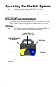
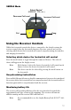
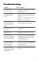
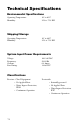
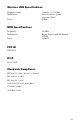
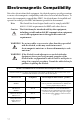
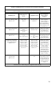
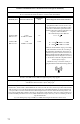
Table Of Contents
- Table of Contents
- Warnings and Cautions
- 1. Read this operating manual thoroughly and be familiar with its contents prior to using this equipment.
- 2. Carefully unpack the unit and check if any damage occurred during shipment. If damage is detected, please refer to the Service section in this manual.
- 3. Avoid removing covers on the unit and attempting internal repairs or adjustments not specifically detailed in this operating manual.
- 4. Pay close attention to the care and cleaning instructions in this manual. A deviation may cause damage to the device.
- 5. Never sterilize the Wireless Universal footswitch components.
- 6. Be completely familiar and comfortable with the operation of the Wireless Universal footswitch. Training may be required before some operators are thoroughly familiar with how to properly operate the footswitch.
- 7. When the Receiver is interconnected with other medical electrical equipment, leakage currents may be additive. Ensure all systems are installed according to the requirements of IEC 60601-1-1.
- Symbol Definitions
- Product Description and Intended Use
- 1. A wireless footswitch, which provides pedals similar to those found on other footswitches and transmits radio signals to a radio receiver console
- 2. A radio receiver console, which routes commands from the footswitch to devices that connect to the receiver’s rear panel.
- The Footswitch
- The Receiver
- Front Panel
- 1. Power Switch: Powers on and off the receiver. The switch will illuminate when the unit is on.
- 2. Synchronize port 1: Enables a footswitch to work with the receiver when aligned with the synchronize logo on that footswitch. The footswitch will be designated as “footswitch 1.”
- 3. Mode button 1: Selects which device footswitch 1 will control (which “mode” the footswitch is in). Pressing and holding this button will clear the Footswitch.
- 4. Active-device display 1: Displays which device is currently active and can be controlled by footswitch 1 (which “mode” footswitch 1 is in).
- 5. Active-device display 2: Displays which device is currently active and can be controlled by footswitch 2 (which “mode” footswitch 2 is in).
- 6. Mode button 2: Selects which device footswitch 2 will control (which “mode” the footswitch is in). Pressing and holding this button will clear the Footswitch
- 7. Synchronize port 2: Enables a second footswitch to work with the receiver when aligned with the synchronize logo on that footswitch. The footswitch will be designated as “footswitch 2.”
- Rear Panel
- 1. TPS output: Provides a dedicated connection to the TPS console, enabling the commands issued from the footswitch to be routed to the TPS console.
- 2. SERFAS output: Provides a dedicated connection to the SERFAS console, enabling the commands issued from the footswitch to be routed to the SERFAS console.
- 3. Expansion port: Provides a generic connection to addition devices, enabling the commands issued from the footswitch to be routed to the console.
- 4. Expansion port: Provides a generic connection to addition devices, enabling the commands issued from the footswitch to be routed to the console.
- 5. SFB Serial Connectors: Enables firewire connection with newer devices, such as CORE and SERFAS Energy, eliminating the need for multiple connection cables.
- 6. Volume control: Controls the output volume.
- 7. AC-power input: Connects to the AC Power cord, which connects to a hospital-grade power outlet.
- Setting up the iSwitch
- footswitch Receiver
- Reverse
- Cut
- Using the Receiver Controls
- Cleaning and Maintenance
- Troubleshooting
- Technical Specifications
- Electromagnetic Compatibility
- Warranty
- Service and Claims
- 1. Contact Stryker Endoscopy at 1-800-624-4422, or phone your local Stryker Endoscopy sales representative.
- 2. Clean and sterilize all parts that will be returned for service. Follow the instructions provided in this manual.
- 3. Package all the components carefully in the original shipping container if possible.
- 4. Ship the unit, pre-paid and insured to:
- Other Service

18
Guidance and Manufacturer's Declaration: Electromagnetic Immunity
iSwitch is intended for use in the electromagnetic environment specified below. The customer or
the user of iSwitch should ensure that it is used in such an environment.
Immunity Test
IEC 60601 Test
Level
Compliance Level
Electromagnetic
Environment:
Guidance
Electrostatic Discharge (ESD)
IEC61000-4-2
±6kV contact
±8kV air
±2,4,6kV contact
±2,4,8kV air
Floors should be
wood, concrete, or
ceramic tile. If floors
are covered with syn
-
thetic material, the rel-
ative humidity should
be at least 30%.
Electrical fast transient/burst
IEC61000-4-4
±2kV for power sup-
ply lines
±1kV for input/out-
put lines
±2kV line to ground
±1kV line to line
Mains power quality
should be that of a typ
-
ical commercial or
hospital environment.
Surge
IEC61000-4-5
±1kV differential
mode
±2kV common mode
±0.5, 1kV differential
mode
±0.5, 1, 2kV common
mode
Mains power quality
should be that of a typ
-
ical commercial or
hospital environment.
Voltage dips, short interrup-
tions and voltage variations on
power supply input lines
IEC61000-4-11
<5% Ut (>95% dip in
Ut) for 0.5 cycle
40% Ut (60% dip in
Ut) for 5 cycles
70% Ut (30% dip in
Ut) for 25 cycles
<5% Ut (>95% dip in
Ut) for 5 sec.
<5% Ut (>95% dip in
Ut) for 0.5 cycle
40% Ut (60% dip in
Ut) for 5 cycles
70% Ut (30% dip in
Ut) for 25 cycles
<5% Ut (>95% dip in
Ut) for 5 sec.
Mains power quality
should be that of a typ
-
ical commercial or
hospital environment.
If the user of iSwitch
requires continued
operation during
power mains interrup
-
tions, it is recom-
mended that iSwitch
be powered from an
uninterruptible power
supply or a battery.
Power frequency (50/60Hz)
magnetic field
IEC 61000-4-8
3 A/m
3 A/m
Power-frequency mag-
netic fields should be
at levels characteristic
of a typical location in
a typical commercial
or hospital environ
-
ment.
NOTE: Ut is the a.c. mains voltage prior to application of the test level.