
User's Manual
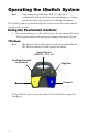
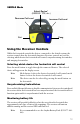
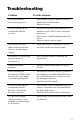
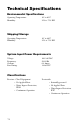
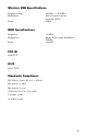
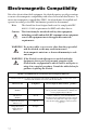
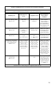
Table Of Contents
- Table of Contents
- Warnings and Cautions
- 1. Read this operating manual thoroughly and be familiar with its contents prior to using this equipment.
- 2. Carefully unpack the unit and check if any damage occurred during shipment. If damage is detected, please refer to the Service section in this manual.
- 3. Avoid removing covers on the unit and attempting internal repairs or adjustments not specifically detailed in this operating manual.
- 4. Pay close attention to the care and cleaning instructions in this manual. A deviation may cause damage to the device.
- 5. Never sterilize the Wireless Universal footswitch components.
- 6. Be completely familiar and comfortable with the operation of the Wireless Universal footswitch. Training may be required before some operators are thoroughly familiar with how to properly operate the footswitch.
- 7. When the Receiver is interconnected with other medical electrical equipment, leakage currents may be additive. Ensure all systems are installed according to the requirements of IEC 60601-1-1.
- Symbol Definitions
- Product Description and Intended Use
- 1. A wireless footswitch, which provides pedals similar to those found on other footswitches and transmits radio signals to a radio receiver console
- 2. A radio receiver console, which routes commands from the footswitch to devices that connect to the receiver’s rear panel.
- The Footswitch
- The Receiver
- Front Panel
- 1. Power Switch: Powers on and off the receiver. The switch will illuminate when the unit is on.
- 2. Synchronize port 1: Enables a footswitch to work with the receiver when aligned with the synchronize logo on that footswitch. The footswitch will be designated as “footswitch 1.”
- 3. Mode button 1: Selects which device footswitch 1 will control (which “mode” the footswitch is in). Pressing and holding this button will clear the Footswitch.
- 4. Active-device display 1: Displays which device is currently active and can be controlled by footswitch 1 (which “mode” footswitch 1 is in).
- 5. Active-device display 2: Displays which device is currently active and can be controlled by footswitch 2 (which “mode” footswitch 2 is in).
- 6. Mode button 2: Selects which device footswitch 2 will control (which “mode” the footswitch is in). Pressing and holding this button will clear the Footswitch
- 7. Synchronize port 2: Enables a second footswitch to work with the receiver when aligned with the synchronize logo on that footswitch. The footswitch will be designated as “footswitch 2.”
- Rear Panel
- 1. TPS output: Provides a dedicated connection to the TPS console, enabling the commands issued from the footswitch to be routed to the TPS console.
- 2. SERFAS output: Provides a dedicated connection to the SERFAS console, enabling the commands issued from the footswitch to be routed to the SERFAS console.
- 3. Expansion port: Provides a generic connection to addition devices, enabling the commands issued from the footswitch to be routed to the console.
- 4. Expansion port: Provides a generic connection to addition devices, enabling the commands issued from the footswitch to be routed to the console.
- 5. SFB Serial Connectors: Enables firewire connection with newer devices, such as CORE and SERFAS Energy, eliminating the need for multiple connection cables.
- 6. Volume control: Controls the output volume.
- 7. AC-power input: Connects to the AC Power cord, which connects to a hospital-grade power outlet.
- Setting up the iSwitch
- footswitch Receiver
- Reverse
- Cut
- Using the Receiver Controls
- Cleaning and Maintenance
- Troubleshooting
- Technical Specifications
- Electromagnetic Compatibility
- Warranty
- Service and Claims
- 1. Contact Stryker Endoscopy at 1-800-624-4422, or phone your local Stryker Endoscopy sales representative.
- 2. Clean and sterilize all parts that will be returned for service. Follow the instructions provided in this manual.
- 3. Package all the components carefully in the original shipping container if possible.
- 4. Ship the unit, pre-paid and insured to:
- Other Service

17
Electromagnetic Compatibility
Like other electrical medical equipment, the iSwitch requires special precautions
to ensure electromagnetic compatibility with other electrical medical devices. To
ensure electromagnetic compatibility (EMC), the iSwitch must be installed and
operated according to the EMC information provided in this manual.
Note The iSwitch has been designed and tested to comply with IEC
60601-1-2:2001 requirements for EMC with other devices.
Caution The iSwitch may be interfered with by other equipment,
including portable and mobile RF communication
equipment,
even if such equipment meets the applicable emissions
requirements.
WARNING Do not use cables or accessories other than those provided
with the iSwitch, as this may result in increased
electromagnetic emissions or decreased immunity to such
emissions.
WAR NI NG If the iSwitch is used adjacent to or stacked with other
equipment, observe and verify normal operation of the
iSwitch in the configuration in which it will be used prior to
using it in a surgical procedure. Consult the tables below for
guidance in placing the iSwitch.
Guidance and Manufacturer's Declaration: Electromagnetic Emissions
iSwitch is intended for use in the electromagnetic environment specified below. The customer or the user of
iSwitch should ensure that it is used in such an environment.
Emissions test Compliance Electromagnetic Environment - guidance
RF emissions
CISPR11
Group 1 The iSwitch must emit electromagnetic energy in
order to perform its intended function. NEarby elec-
tronic equipment may be affected.
RF emissions
CISPR11
Class B iSwitch is suitable for use in all establishments,
including domestic establishments and those directly
connected to the public low-voltage power supply
network that supplies buildings used for domestic
purposes.
Harmonic emissions
IEC61000-3-2
Class A
Voltage Fluctuation s/
flicker emissions
IEC61000-3-3
Complies