2-TON HYDRAULIC ENGINE CRANE OWNER’S MANUAL WARNING: Read carefully and understand all ASSEMBLY AND OPERATION INSTRUCTIONS before operating. Failure to follow the safety rules and other basic safety precautions may result in serious personal injury.
Thank you very much for choosing a Strongway product! For future reference, please complete the owner’s record below: Model: _______________ Purchase Date: _______________ Save the receipt, warranty and these instructions. It is important that you read the entire manual to become familiar with this product before you begin using it. This machine is designed for certain applications only. The distributor cannot be responsible for issues arising from modification.
TECHNICAL SPECIFICATIONS LAYOUT GENERAL SAFETY RULES WARNING: Read and understand all instructions. Failure to follow all instructions listed below may result in serious injury. CAUTION: Do not allow persons to operate or assemble this Hydraulic Engine Crane until they have read this manual and have developed a thorough understanding of how the Hydraulic Engine Crane works.
SAVE THESE INSTRUCTIONS IMPORTANT SAFETY CONSIDERATIONS HYDRAULIC ENGINE CRANE USE AND CARE Do not modify the Hydraulic Engine Crane in any way. Unauthorized modification may impair the function and/or safety and could affect the life of the equipment. There are specific applications for which the Hydraulic Engine Crane was designed. Always check of damaged or worn out parts before using the Hydraulic Engine Crane. Broken parts will affect the Hydraulic Engine Crane operation.
* Position the Crane Position the crane to only lift on the areas of the vehicle as specified by the vehicle manufacturer. * Do Not Overload Crane Do not overload this crane beyond its rated capacity. Overloading this crane beyond its rated capacity can cause damage to or failure of the crane. * Always Use on Hard Level Surfaces This crane is designed only for use on hard level surfaces capable of sustaining the load. Use on unstable or other possible loss of load.
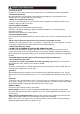
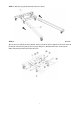
ASSEMBLY STEP 1. Fasten the two larger rear caster wheels (No.33) on the Base structure with Bolts (No.30), washers (No.24) and nuts (No.31.) (Face bolts up when installing.) Fasten the smaller two caster wheels (No.32) on the Base structure with Bolts (No.29), washers (No.24). (Face bolts up when installing.) STEP 2. Fasten the remaining larger two caster wheels (No.33) on the front legs (No.2) with bolts (30), washers (No.24) and nuts (No.31.
STEP 3. Slide the legs (No.2) into front of the base (No.1). STEP 4. Fasten the guide plates (No.35), to the base frame (No.1) and front legs (No.2) with bolts (No.18), washers (No.22) and nuts (No.25). Lift one side of the base to align the hole on the frame to the hole on each front leg (No.2), then insert the Ring Pins (No.28) into the hole, and insert the Cotter-Pin (No.36) into the hole of the Ring Pins.
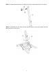
STEP 5. Use Bolts (No.29) and Washers (No.24) to fasten the Handle (No.34) to the Post (No.9). STEP 6. Use two Bolts (No.14), washers (No.21) and Nuts (No.27) to connect the bottom of the Post (No.9) to the Base Frame (No.1).
STEP 7. Use two Bolts (No.17), Washers (No.23) and Nuts (No.26) to connect the lower ends of the Supports (No.5) to the inside of the base (No.1). Then use Bolt (No.15), Washer (No.23) and Nut (No.26) to connect the top ends of the Supports to the post (No.9),check to make sure the nuts were tightened,and tighten the nuts in step 6. STEP 8. Use Bolt (No.10), Washer (No.19) and Nut (No.25) to attach the Boom (No.3) to the top of the Post (No.9) ,tighten Nut (No.25) so that the boom (No.
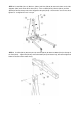
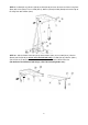
STEP 9. Use Bolt (No.12), Washer (No.20) and Nut (No.26) to fasten the lower end of the Long Ram (No.6) to the Post (No.9). Then use Bolt (No.13), Washer (No.20) and Nut (No.26) to fasten the top of the Long Ram to the Boom (No.3). STEP 10. Slide the Boom Extension (No.4) into the Boom (No.3) and use Bolt (No.11), Washer (No.20) and Nut (No.26) to secure at the desired load rating. Use Bolt (No.16), Washer (No.21) and Nut (No.27) to attach the Hook and Chain (No.8) to the end of the Boom Extension.
SYSTEM AIR PURGE PROCEDURE IMPORTANT: BEFORE FIRST USE Before initial use and over time it is possible that air will enter the hydraulic system, causing poor lifting performance. Perform the following Air Purge Procedure to remove any air that may have been introduced into the hydraulic system as a result of product shipment and handling. This step is to be completed without any weight on the crane. 1. Turn release valve counterclockwise on full turn to the open position. 2.
4. With a flat blade screwdriver, push the oil fill plug slightly to the side to purge trapped air from system. (Use caution not to tear or puncture the oil plug.) 5. Turn release valve clockwise to the closed position. 6. Crane is now ready for use. Check for proper pump action.
OPERATING INSTRUCTIONS BEFORE USE 1. Before using this product, read the owner's manual completely and familiarize yourself thoroughly with the product and the hazards associated with its improper use. 2. Perform the air purge procedure. (See previous instructions for system purge procedure.) 3. Check and that the pump operates smoothly before putting into service. 4. Inspect before each use. Do not use if bent, broken or cracked components are noted.
HYDRAULIC OPERATION 1. Familiarize yourself with the crane 2. Attach the handle piece, making sure to align with lowering valve, turn CLOCKWISE until tight. 3. Line up the handle to the handle socket located on the side of the long ram, then insert the handle inside the handle socket. 4. Secure the handle in place inside the handle socket. Without any on the crane. Cycle the lift up and down several times to insure the hydraulic system is operating properly.
RAISING THE CRANE 1. Block the vehicle’s wheels for lifting stability. Secure the load to prevent inadvertent shifting and movement 2. Position the crane near desired lift point. 3. Set the Parking Brake in the vehicle. 4. Close the release valve by turning it clockwise until it is firmly closed. 5. Before raising the load double check and verify the load is centered and also has full contact with the lifting point. 6. Pump handle to lift load.
LOWERING THE CRANE 1. Raise load high enough to allow for clearance. 2. Grasp the handle firmly with both hands. Securely hold on to the long ram handle so your hands do not slip and ensure the release valve does not rapidly lower. 3. Carefully open the Release Valve by slowly turning the handle counterclockwise. (Do not allow bystanders around the crane or under the load when lowering the crane. 4.
MAINTENANCE INSTRUCTIONS If you use and maintain your equipment properly, it will give you many years of service. Follow the maintenance instructions carefully to keep your equipment in good working condition. Never perform any maintenance on the equipment while it is under a load. Inspection You should inspect the product for damage, wear, broken or missing parts (e.g.: pins) and that all components function before each use. Follow lubrication and storage instructions for optimum product performance.
TO ADD OIL: 1. Open the Release Valve by slowly turning the handle counterclockwise and lower ram to it’s lowest position. 3. With long ram in the vertical position Fill the oil case until oil level is just beneath the lower rim of the oil fill hole. 2. Remove the oil plug. 4. Replace oil plug. 5. Perform the Air Purge Procedure. *SEE ASSEMBLY IMAGE FOR OIL RESEVOIR LOCATION.
TO REPLACE OIL: 1. Open the Release Valve by slowly turning the handle counterclockwise and lower ram to it’s lowest position. 2. Unscrew and remove bolts and nuts as show in image below and remove the long ram (No.6). Remove the long ram (6). Note: Use caution when removing long ram.
3. Remove the oil fill plug. 4. Turn the long ram on its side to drain old oil from the oil fill hole. 5. Position the long on level ground in the vertical position and keep hydraulic ram in the lowered position. 6. Fill the oil case until oil level is just beneath the lower rim. KEEP DIRT AND OTHER MATERIAL CLEAR WHEN POURING.
7. Replace oil plug. 8. Re-Install long ram (6) into frame. (See Step 2 and 3.) 9. Tighten Hardware Removed. 10. Perform the Air Purge Procedure.
ADDITIONAL WARNINGS: DO NOT USE MOTOR OIL IN THE CRANE. ONLY USE ANTI-FOAMING JACK OIL. ALWAYS USE A GOOD GRADE HYDRAULIC JACK OIL. DO NOT USE HYDRAULIC BRAKE FLUID, ALCOHOL, GLYCERINE, DETERGENT, MOTOR OIL OR DIRTY OIL. USE OF A NON-RECOMMENDED FLUID CAN CAUSE DAMAGE TO A CRANE. AVOID MIXING DIFFERENT TYPES OF FLUID AND NEVER USE BRAKE FLUID, TURBINE OIL, TRANSMISSION FLUID, MOTOR OIL OR GLYCERIN.
ASSEMBLY DIAGRAM 23
ASSEMBLY PARTS LIST Index # 1 2 3 4 5 6 7 8 9 10 11 12 Description Base frame Front leg Boom Boom extension Support strap Hydraulic ram Pump handle Hook chain Main chain assembly Bolt M18x110 Bolt M16x90 13 Bolt M16x75(8.8) Bolt M14x100 Bolt M16x110 14 15 16 17 18 19 20 21 22 23 24 25 26 27 28 29 30 31 32 33 34 35 36 Part No. T32002X.1 T32002X.4 T32002X.3 T32002X-3 T32002X-2 T30506X.0 QYL5-23 T32002.5 T32002X.2 GB5780 GB5780 GB5782 Bolt M16x90(8.8) Bolt M14x75(8.
HYDRAULIC LONG RAM ASSEMBLY DIAGRAM 25
HYDRAULIC LONG RAM PARTS LIST Index # 1 2 3 4 5 6 7 8 9 10 11 12 13 14 15 16 17 18 19 20 21 22 23 24 25 26 27 28 29 30 31 32 Description Ram Wire ring Ram Split washer Y-Ring Wire ring Cylinder Copper Washer Tube Ball Copper Washer Pump Cylinder Seal Ring O-Ring Back up Ring Plunger Pin R-Ring Handle Socket Handle O-Ring Top Nut Sealing Gasket Oil Tank Oil Plug Seal Ring Release Spindle O-Ring Safety Cap Plug Screw O-Ring Spring Part No.
Limited Warranty Limited Warranty Northern Tool and Equipment Company, Inc. ("We'' or '"Us'') warrants to the original purchaser only ("You'' or “Your”) that the Strongway product purchased will be free from material defects in both materials and workmanship, normal wear and tear excepted, for a period of one year from date of purchase. The foregoing warranty is valid only if the installation and use of the product is strictly in accordance with product instructions.