Electric Chainsaw Sharpener With Hydraulic Assist Owner’s Manual WARNING: Read carefully and understand all ASSEMBLY AND OPERATION INSTRUCTIONS before operating. Failure to follow the safety rules and other basic safety precautions may result in serious personal injury.
Thank you very much for choosing a Strongway™ product! For future reference, please complete the owner’s record below: Serial Number/Lot Date Code: ________________________________ Purchase Date: ____________________________________________ Save the receipt, warranty, and this manual. It is important that you read the entire manual to become familiar with this product before you begin using it. This sharpener is designed for certain applications only.
Table of Contents Intended Use .......................................................................................................................................... 4 Technical Specifications ...................................................................................................................... 4 Important Safety Information ............................................................................................................... 4 Specific Operation Warnings .......................
Intended Use The Strongway Electric Chainsaw Sharpener with Hydraulic Assist is designed for sharpening most chainsaws. Technical Specifications Property Supply voltage Motor input power Chain Pitch Maximum speed Weight Specification 110 Volt/60 Hz 2.7 Amps (300 Watts) ¼ Inch to ¾ Inch 3400 RPM 21 lb. Important Safety Information ⚠WARNING Read and understand all instructions. Failure to follow all instructions may result in serious injury or property damage.
and contact will cause electrical shock. Keep children and bystanders away from the work area while operating the tool. Do not allow children to handle the product. ⚠WARNING PERSONAL SAFETY Stay alert, watch what you are doing, and use common sense when operating the tool. Do not use the tool while you are tired or under the influence of drugs, alcohol, or medication. A moment of inattention while operating the tool may result in serious personal injury. Dress properly.
another tool. Never use an accessory that has a lower operating speed or operating pressure than the tool itself. Keep guards in place and in working order. Never operate the product without the guards in place. Do not leave the tool running unattended. Specific Operation Warnings ⚠WARNING Wear the proper protective equipment including ANSI Z87.1 compliant eye protection, NIOSH compliant breathing protection, and hearing protection.
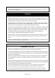
Tools marked with Grounding Required have a 3-wire cord and 3-prong grounding plug. The plug must be connected to a properly grounded outlet. If the tool should electrically malfunction or break down, grounding provides a low resistance path to carry electricity away from the user, reducing the risk of electric shock. (See Figure A.) The grounding prong in the plug is connected through the green wire inside the cord to the grounding system in the tool.
As the distance from the supply outlet increases, you must use a heavier gauge extension cord. Using extension cords with inadequately sized wire causes a serious drop in voltage, resulting in loss of power and possible tool damage. The smaller the wire’s gauge number, the greater the capacity of the cord. For example, a 14gauge cord can carry a higher current than a 16-gauge cord.
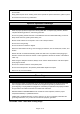
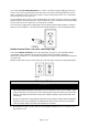
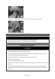
1. When installing it on a bench, place the sharpener on the edge of the bench to the stop (Fig. 1) and screw it to the desk using the holes in the base. 2. When mounting on the wall, use the respective holes in the vertical part of the base. 3. After the bench top installation, fit the arm in the base, inserting the pilot pin and securing it with a hexagonal screw (Fig.2). 4. Now, fit a washer (included) on the rear side screw and screw on the setting wheel (Fig.3). 5.
7. To be able to install the disc, it is necessary to unscrew the auxiliary flange (Fig.6). Before Each Use ⚠WARNING Inspect the whole condition of the sharpener for good working condition. Check the disc you are about to use for damages prior to installation. Operating Instructions ⚠WARNING Wear the proper protective equipment including ANSI Z87.1 compliant eye protection, NIOSH compliant breathing protection, and hearing protection.
When using the sharpener outdoors, always use an outdoor rated extension cord with a splashproof plug and socket. Do not use a caustic solution to clean plastic parts. Do not use the sharpener in the proximity of flammable liquids and vapors. Not for use by or around children. Easy-to-use controls to make precise adjustments Hydraulic piston automatically compresses chain vise to increase efficiency. Hydraulic assist closes the chain vise automatically when the motor and wheel are lowered.
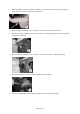
As always, be careful while working. Grinding 1. With the clamping screw adjusted, the vise angle set up (Note: RH and LH teeth to be differentiated), and the top plate angle preset, lower the grinding disc to the tooth. The grinding depth may reset by adjusting the set screw (K). 2. Some types of chains require that the clamping screw be tilted by 5°-10°. 3. Now, the machine may be switched on and the chain grinding may be started by gently pressing the disc on the chain.
Maintenance Maintain the sharpener by adopting a program of conscientious repair and maintenance in accordance with the following recommended procedures. It is recommended that the general condition of any tool be examined before it is used. Keep your tool in good repair. Keep all cutting tools sharp and clean. Properly maintained cutting tools with sharp cutting edges are less likely to bind and are easier to control. Keep handles dry, clean, and free from oil and grease.
Parts Diagram Parts List Reference 1 2 3 4 5 6 7 8 9 10 11 12 13 14 Part Description Handle Hex Nut M6 Motor Holder Switch Adjusting Bolt M8 Adjusting Nut M8 Rubber MatM8 Big Tensional Spring Shaft Sleeve Shaft Stand Base Flat Washing 11*28*2.
Reference 15 16 17 18 19 20 21 22 23 24 25 26 27 28 29 30 31 32 33 34 35 36 37 38 39 40 41 42 43 44 45 46 47 48 49 50 51 52 53 54 55 56 57 58 59 60 61 62 63 64 65 66 67 Part Description Hex Screw M5*22 Small Pressure Spring A Flat Washing 5*1 Hex Nut M5*22 Guide Wheel A Rubber Mat M6 Adjusting Nut M6 Adjusting Screw M6 Out Plate Inner Plate Steel Ball 4 Small Pressure Spring C Cam Flat Mat 5*15*1 Dial Bottom Bolt M5*10 Fixed Stand A Small Pressure Spring D Lock Ring Guide Cover Big Tensional Spring Positio
Replacement Parts For replacement parts and technical questions, please call Customer Service at 1-800-222-5381. Not all product components are available for replacement. The illustrations provided are a convenient reference to the location and position of parts in the assembly sequence. When ordering parts, the following information will be required: item description, item model number, item serial number/item lot date code, and the replacement part reference number.
Limited Warranty Northern Tool and Equipment Company, Inc. ("We'' or "Us'') warrants to the original purchaser only ("You'' or "Your") that the Strongway product purchased will be free from material defects in both materials and workmanship, normal wear and tear excepted, for a period of one year from date of purchase. The foregoing warranty is valid only if the installation and use of the product is strictly in accordance with product instructions.
Distributed by: Northern Tool & Equipment Company, Inc. Burnsville, Minnesota 55306 www.northerntool.com Made in China.