
User's Manual

Page 7
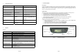
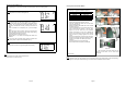
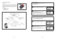
5. DISPLAY/RECEIVER MODULE
Figure 8 LCD Display
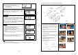
Installation
1. Insert the Power Supply Cable connector into Receiver socket,
which is located at the top rear. (Figure 9 &10).
2. Connect the other end of the Power Supply Cable to the vehicle
+12VDC, Ground and ACC.
Figure 9 Connection of Power Cable
RED color wire to vehicle +12V DC,
BLACK color wire vehicle Ground,
ORANGE color Wire to vehicle ACC,
Figure 10 Wiring Diagram
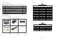
Sensor Battery Status
User setting selected.
ID learning mode.
Backlight selection.
Temperature in °C.
Temperature in °F
ID exchange mode.
Tire monitor mode.
Pressure alert icon.
Pressure in Kpa
Pressure in Psi
Pressure in Bar.
Measured Temperature
Readout
Rear Right Tire
Front Right Tire
Measured Pressure
Readout
Front Left Tire
Rear Left Tire
Spare Tire
Page 12
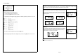
Sensor ID Exchange
Mode (S- 3)
After rotation of tires, the Sensor ID data in the receiver must be changed accordingly to ensure that it indicates
the correct tire when there are any irregularities.
Step 1
Press [OK] button to enter ID Exchange mode.
Figure 31
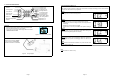
Step 2
The Front left tire icon and its corresponding ID digit will blink.
1. Use [+] and [-] button to change the selected Sensor ID digit.
2. Press [OK] to confirm the changes and the next ID digit will blink
accordingly.
3. Repeat step 1 and 2 for all other ID digits.
4. The ID number ‘5’ will only be available if the spare tire setting is
‘ON’
Figure 32
Step 3
Press [T] button to quit the ID Exchange mode without saving and
return back to Programming Main menu display.
Figure 33
Step 4
The receiver will return back to Programming Main menu display and
that complete the process of exchanging Sensor ID data in the
receiver.
Note
The receiver will not save the information if any of the tires are found
to have identical Sensor ID.
Figure 34
Note
1. Value shown is for reference only.