
User's Manual

Page 11
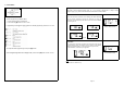
Programming Threshold Setting (S- 2)
Press [OK] to enter the Threshold setting mode.
There are two available threshold setting mode available,
1. User setting (USr)
2. Factory Default (FAC) Figure 25
Upon entering this mode, the selected threshold setting mode will
blink, indicating that the currently selected mode and it is ready to
accept changes of the mode. Pressing the [ + ] button or [ - ] button to
toggle the mode to USr or FAC. (refer figure 26)
Figure 26
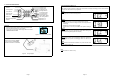
Factory Default
To use the factory default mode, toggle [+] or [-] button till the ‘FAC’
setting blinks.
1. Press [OK] to view the factory default for High Pressure Alert,
2. Press [OK] second time for Low pressure Alert and press [OK] the
third time for Temperature threshold alert. Finally press [OK] again
to accept and select the Factory default setting.
Note
All TPMS unit comes with a factory-preset value of 120 Kpa (23 Psi)
for the Low Pressure Alert, 300 Kpa (44 Psi) for High-pressure alert
and 80ºC (176ºF) for the High Temperature Alert.
Figure 27
User Setting
1. To use the User setting mode, toggle [+] or [-] button till the ‘USr’
setting blinks.
2. Press [OK] to enter user setting programming mode. The 1
st
digit
of High Pressure alert will blink. (Figure 28)
3. Toggle [+] or [-] button to make the value changes.
4. Press [OK] to confirm the changes. The next digit will blink to
indicate that it is ready to accept new input.
5. Repeat steps 3 and 4 to adjust the value of other digits on the LCD
display.
6. Repeat step 2 to step 5 for both Low Pressure Alert (Figure 29)
and High temperature alert (Figure 30).
Note
For low and high pressure alert, the maximum limit is 399Kpa (58 Psi)
while for temperature; the maximum limit is 99ºC (210ºF).
To confirm the selected value, press the [OK] button to save it.
Figure 28
Figure 29
Figure 30
Note
1. Value shown is for reference only.
2. The setting of Manual Threshold Setting can only be done in Kpa (Pressure) and ºC (Temperature).
Refer to Annex 1 & 2 for conversion between the units.
Page 8
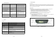
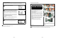
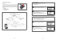
Recommended Installation for Display/Receiver Module and Bracket
Figure 11
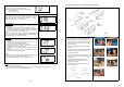
1. Determine the desired location for Display/Receiver
Module. Refer Figure. 12 for possible locations
2. Peel off the film covering the piece of black adhesive
double-sided-tape film on the back of the display
bracket. (Figure 13)
3. Mount the Display Module to the desired location.
(Figure 14)
4. Apply pressure around the Display/Receiver Module
for maximum mounting of the module to the car
windscreen. (Figure 15)
5. If the module did not fix well to the windscreen, take
out the Display module from the bracket. (Figure 16
and Figure 17)
6. Apply pressure around the bracket panel for
maximum mounting of the bracket to the car
windscreen. (Figure 18)
7. Install back the Display/Receiver module to the
bracket. (Figure 19)
Figure 12
Figure 13 Figure 14
Figure 15 Figure 16
Figure 17 Figure 18
Figure 19