
User's Manual


Page 13
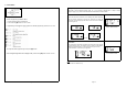
Sensor ID Learning
Mode (S- 4)
For programming of a new receiver unit with ID Learning Mode, refer to the following steps.
Step 1
Press [OK] button to enter the ID learning Mode.
Figure 35
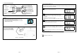
Step 2
1. The front left tire icon will blink. Toggle [+] or [-] button to
select the desired tire and press [OK] to accept the desired
location. The corresponding tire ID number blinks (once per
second) to indicate that it is ready to accept new Sensor ID
input.
2. Inflate or deflate the corresponding tire by at least 28Kpa
(4Psi).
3. When the new ID code is received, the tire icon will blink at a
faster rate (twice per second); the ID number stops blinking
and the module will beep for 5 second.
4. Press [OK] button to save the sensor ID.
5. Repeat Step 1 to 3 for other tire sensor(s) that needs to be
replaced.
Note
ID ‘5’ will only be able to receive sensor signal if the Spare Tire
setting is ON. (Refer to Spare Tire On/Off
Mode (S- 6))
Figure 36
Step 3
Press [T] button to return to Programming Main menu display.
Figure 37
Note
1. The receiver will not save any identical Sensor ID.
2. Value shown is for reference only.
Page 6
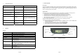
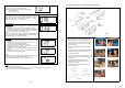
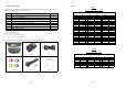
Installing Sensor/Transmitter Module
Note
Ensure that each of the color tag correspond to the color label on the sensor. Refer Table 5 for the corresponding
sensor tag to tire. Keep the colored sensor tag on the valve stem for installation and tire rotation.
The following is suggested installation sequence:
Transmitter Wheel Position
Red (1) Left Front
Yellow (2) Right Front
Blue (3) Right Rear
Green (4) Left Rear
White (5) *Spare Tire
Table 5
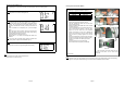
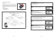
• Remove the original tire valve from tire rim.
• Insert the provided tire valve into rim valve hole.
(Figure 3a & Figure 3b.)
• Position the Sensor/Transmitter rear to the mounted
tire valve. (Figure 4),
• Insert the provided screw to the Sensor as shown in
figure 5 and screw the Sensor to the tire valve.
(Figure 6). The tire valve will be the reference
position of the sensor in order not to damage the
sensor when removing tire from the wheel. Ensure
that the screw is properly tightened to hold the
sensor.
• Attach the corresponding color tag to the valve stem
and secure it with the valve cap by carefully twisting
the tag onto the valve stem. See Figure 7a and
Figure 7b.
• Proceed to mount the tire onto the wheel.
• Ensure that the tires are properly re-balanced.
*Optional Part
Figure 3a Figure 3b
Figure 4 Figure 5
Figure 6 Figure 7a
Figure 7b
# = The tag (Figure.7a) has the same color and
number as the same as the sensor label
(Figure.7b).
#