StorCase® Technology Data Express® Ultra320 DE100 Removable SCSI Wide Ultra320 Drive Enclosure User's Guide
i StorCase® Technology Data Express® Ultra320 DE100 Removable SCSI Wide Ultra320 Drive Enclosure User's Guide Part No. D89-0000-0225 A00 May 2003 StorCase Technology, Inc. 17600 Newhope Street Fountain Valley, CA 92708-9885 Phone (714) 438-1850 Fax (714) 438-1847 Ultra320 DE100 User's Guide - Rev. A00 StorCase Technology, Inc.
ii LIMITED WARRANTY STORCASE TECHNOLOGY, Incorporated (StorCase) warrants that its products will be free from defects in material and workmanship, subject to the conditions and limitations set forth below. StorCase will, at its option, either repair or replace any part of its product that proves defective by reason of improper workmanship or materials.
iii Free Technical Support StorCase provides free technical support. If you experience any difficulty during the installation or subsequent use of a StorCase product, please contact StorCases Technical Support Department prior to servicing your system. This warranty covers only repair or replacement of defective StorCase products, as described above. StorCase is not liable for, and does not cover under warranty, any costs associated with servicing and/or installation of StorCase products.
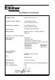
iv Declaration of Conformity Company Name: StorCase Technology, Inc.
v Table of Contents INTRODUCTION ........................................................................................................................ Packaging Information ................................................................................................... Serial Numbers ............................................................................................................... Package Contents ...........................................................................................
vi List of Figures Figure 1: Figure 2: Figure 3: Figure 4: Figure 5: Figure 6: Figure 7: Figure 8: Figure 9: Figure 10: Figure 11: Package Contents ............................................................................................... 2 Ultra320 DE100 Receiving Frame and Carrier ................................................... 3 Receiving Frame Front Panel .............................................................................. 4 Receiving Frame Unit ID Number and Activity Display ......
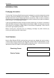
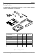
Introduction 1 INTRODUCTION Packaging Information The StorCase Technology Data Express® system is shipped in a container designed to provide protection and prevent damage during shipment. The Data Express unit was carefully inspected before and during the packing procedure at the factory. Bent or broken connectors, or evidence of other damage to the Data Express should be reported to the shipper immediately. Refer to Figure 1 for the package contents.
2 Introduction Package Contents The DE100 package contents include the following items. If any item is missing or damaged, contact your StorCase dealer for a replacement. 3 5 6 7 4 9 Da ta E I/O ID Driv e Car Sel rier ect Dis (No k Driv t Incl e ude d) Pow er Cab le le 8 2 xpr ess Cab Cov (Pro er le vide d) Cab Cab le Driv Har e Phi 3/16 llipsdwareMountin Flat # 6-3(4e g HD 2 x a) 0151 Cab Scr le # Flat 6-32ews (2Cover HD x 3/16plcs ) 0430P 1 Carrier & Rec. Frame Carrier Only 1.
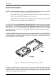
Introduction 3 General Description NOTES: For SCSI Ultra320 operation, the Ultra320 DE100 requires Ultra320 drives, Ultra320 HBA, and Ultra320-compliant cabling (internal and external). Ultra320 DE100 can support Ultra320 implementations with a maximum of fifteen (15) Ultra320 drives (Ultra320 repeater may be required). Ultra320 DE100 receiving frames are indicated by their BLUE LED, while the Ultra320 DE100 carriers are indicated by the Ultra320 logo.
4 Introduction Receiving Frame Front Panel (Figure 3) Key Lock/Drive Power Switch - This key switch assures proper seating of the drive carrier within the receiving frame, turns power to the drive carrier ON and OFF, and prevents unauthorized removal or installation of the carrier. For the computer to access data on the disk drive, the key must be turned counterclockwise to the locked position. The key can be permanently attached to the locking mechanism as shown in Appendix C.
Introduction 5 Figure 4: Receiving Frame Unit ID Number and Activity Display Receiving Frame Rear Panel (Figure 5) I/O Connector (J3) : The input/output connector provides a standard interface for all SCSI signals. DC Power Connector (P1): The Ultra320 DE100 uses a standard 4-pin DC power connector to accept DC power. Option Pin Connector (W1): Remote Unit ID Selection: Pins 1-8 of this connector are provided for remote unit SCSI ID selection through the computer system.
6 Introduction W2 Jumper (Factory Installed Do Not Remove!) DC Power Connector (P1) Option Pin Connector (W1) P1 J3 I/O Connector (J3) Remote Activity LED 0501E Remote ID Select ID0 ID1 ID2 ID3 Ultra320 DE100 Pins 11-22 Reserved Figure 5: Receiving Frame (Rear View) StorCase Technology, Inc. Ultra320 DE100 User's Guide - Rev.
Installation 7 INSTALLATION Installing the Drive into the Carrier Preparation While performing the steps in this section, work on a soft surface to prevent excessive shock to the drive being installed. Also refer to the manufacturer's documentation provided with the drive. NOTE: A #2 Phillips screwdriver will be required during this procedure. 1. Remove the drive from its protective packaging. 2. Plastic Drive Bezel: If the drive came equipped with a plastic front bezel, it must be removed. 3.
8 Installation Installation 1. Attach the I/O cable from the rear distribution board of the Ultra320 DE100 carrier to the disk drive (Figure 6). 2. Attach the 4-pin DC power cable from the rear distribution board to the disk drive (Figure 6). 3. Install the 5-pin ID select cable into the rear signal distribution board connector. Refer to Figure 7 for a typical 2mm drive pin connection. 4. Carefully insert the drive into the carrier at an angle, cable-end first.
Installation 9 TYPICAL 2MM DRIVE ID PIN CONFIGURATION Figure 7 illustrates a typical ID select connection to a drive with 2mm ID select pins. The wires on the wire harness connect to the positive pin (or signal pins) on the disk drive. In some cases, the drive manufacturer will label the signal pins as Pin 1, 3, 5, and 7 (instead of 0, 1, 2, 3 as shown in Figure 7 below). Also, in some cases, the even-numbered Pins 2, 4, and 6 are used for Ground.
10 Installation Installing the Receiving Frame The drive should be installed into the carrier before installing the receiving frame into the mounting bay of a computer or expansion chassis. NOTE: Use a #2 Phillips screwdriver during this procedure. 1. Turn OFF power to the computer. 2. Open the computer system according to the manufacturers instructions. If necessary, temporarily remove any expansion boards that may make installation difficult. 3.
Installation 11 ID0 Pin 2 ID1 Pin 4 ID2 Pin 6 ID3 Pin 8 RLED Pin 10 RESERVED Pin 12 RESERVED Pin 14 RESERVED Pin 16 RESERVED Pin 18 RESERVED Pin 20 RESERVED Pin 22 0427u Figure 8: Receiving Frame Motherboard Option Pins (W1) Ultra320 DE100 User's Guide - Rev. A00 StorCase Technology, Inc.
12 Installation IMPORTANT NOTE: In order to use remote ID selection from a computer or expansion chassis, the Unit ID number on the Ultra320 DE100 receiving frame must be set to "0" with the provided alignment tool. Refer to the section "Selecting the Unit ID Number" later in this manual for the Unit ID selection procedure. 4. With the drive carrier locked in place inside the receiving frame, install the Ultra320 DE100 into the 5.25 drive opening in the computer or expansion chassis.
Installation 13 8. Connect the power cable from the DC power supply in the computer or expansion chassis to the power connector on the Ultra320 DE100 receiving frame. Refer to Figure 5 for the Ultra320 DE100 receiving frame power connector location. 9. Replace any expansion boards that may have been removed earlier. Replace the system cover according to the manufacturers instructions. 10. Reconnect any system or peripheral cables removed earlier. 11. Turn ON power to the computer.
14 Installation NOTE: 5. The lock on the Ultra320 DE100 receiving frame serves two functions: 1) as a lock to secure the drive, and 2) as a DC power switch for the carrier unit. The lock must be engaged (turned counterclockwise) in order to supply power to the drive carrier. The new drive may need to be formatted or initialized prior to use with the operating system and applications software. Refer to the drive and/or computer manufacturer's documentation for formatting information.
Installation 15 Adjusting the Spin Down/Up Timer The timer for device spin down is controlled by a small selector, located in a cutout on the side of the Ultra320 DE100 receiving frame as shown in Figure 11. When the key is turned to the OFF position, and when the timer receives a NO SCSI Activity signal from the Isolator Board, it waits the specified delay time before displaying a u on the front panel of the receiving frame.
16 Appendix A - Specifications/Dimensions APPENDICES StorCase Technology, Inc. Ultra320 DE100 User's Guide - Rev.
Appendix A - Specifications/Dimensions 17 Appendix A - Specifications/Dimensions SCSI Data Express subsystems conform to the Small Computer Systems Interface (SCSI) Standard set by the American National Standards Institute (ANSI).
18 Appendix A - Specifications/Dimensions Receiving Frame with Carrier 2.06 (52.3mm) 3.13 (79.5mm) 0.50 (12.7mm) #6-32 x 8 0.38 (9.7mm) 1.70 (43.2mm) 5.75 (146.1mm) 8.18 (207.8mm) 0.52 (13.2mm) 5.50 (139.7mm) 0.25 (6.4mm) 3.13 (79.5mm) 0.64 (16.3mm) #6-32 x 4 Bottom 0285F Carrier Only 1.68 (42.7mm) 7.38 (187.5mm) 3.75 (95.3mm) 4.67 (118.6mm) 1.75 (44.5mm) 0.25 (6.4mm) Figure A-1: Ultra320 DE100 Physical Dimensions (Dimensions are for reference only) StorCase Technology, Inc.
Appendix B - Factory-Installed Options 19 Appendix B - Factory-Installed Options Solenoid Drive Lock The factory-installed solenoid option prevents premature removal of the carrier and drive unit until the target drive has fully spun down. For most disk drives, this period of time can range from 15-40 seconds, depending on the type of drive being used (e.g. Seagate Barracuda drives require up to 45 seconds). Refer to the drive manufacturer's documentation for specific drive information.
20 Appendix C - Attaching the ON/OFF Key Appendix C - Attaching the ON/OFF Key to Non-Solenoid Units The following information will provide the necessary steps to attach the ON/OFF key to the key lock mechanism so that it is non-removable, preventing accidental key loss. The procedure can be reversed to revert back to a removable key, if so desired. 1. Make certain power is OFF to the receiving frame. Locate the rectangular-shaped key lock mechanism access hole on the inside of the receiving frame.
Appendix D - Optional Accessories 21 Appendix D - Optional Accessories Carrying Case Drive Carrier DX100-DE-C Carrying Case 0014 Figure D-1: Carrying Case The optional molded plastic carrying case is designed to transport one (1) Ultra320 DE100 carrier from one site to another in a safe, impact and moisture resistant environment. Its compact dimensions, 7 long x 9 wide x 4 high, make it easy to carry and to store. The foam lining is contoured to fit a single Data Express carrier.
22 Appendix D - Optional Accessories Drive Cover 1 Slip Drive Cover Lip into Top Rear of Carrier. The Sides of the Cover Will Fit Between the Drive and the Carrier. Mounting Holes Must be Towards Rear of Carrier. 1 3 Slide Drive Cover Forward Making Certain Front Cover Lip is Inside Carrier. Fasten Screws. 2 Drive Cover 3 2 Swing Drive Cover Down, Covering the Drive. Make Certain You Do Not Damage Connector Pins or Cables.
Reader's Comments 27 Reader's Comments Please take a few moments when your computer system is up and running to send us your ideas and suggestions for improving our products and documentation.
Reader's Comments CUT ALONG THIS LINE FROM BOTTOM TO TOP OF PAGE 28 FOLD ALONG THIS LINE AND STAPLE SHUT NO POSTAGE NECESSARY IF MAILED IN THE UNITED STATES B U S I N E S S R E P LY M A I L FIRST CLASS MAIL PERMIT NO. 10686 SANTA ANA, CA POSTAGE WILL BE PAID BY ADDRESSEE TECHNOLOGY CORPORATION 17600 NEWHOPE STREET FOUNTAIN VALLEY CA 92708-9885 StorCase Technology, Inc. Ultra320 DE100 User's Guide - Rev.