
User guide

10 Installation
StorCase Technology, Inc. S20A133 User's Guide - Rev. A02
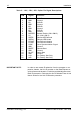
PIN Signal Function
1 ID0 SCSI ID
2 GND Ground
3 ID1 SCSI ID
4 GND Ground
5 ID2 SCSI ID
6 GND Ground
7 ID3 SCSI ID
8 GND Ground
9 BUZZER Buzzer Enable (J3A1 ONLY)
10 5V 5V (J3A1 ONLY)
11 RLEDC Remote LED Cathode
12 RLEDA Remote LED Anode
13 FFAULT Fan Failure Indication
14 FFAULT Fan Failure Indication
15 SYNC Drive Synchronization Signal
16 GND Ground
17 RMTST Remote Start
18 GND Ground
19 DLYST Delay Start
20 GND Ground
21 LKA For Factory Use Only
22 LKB For Factory Use Only
Table 2: J3A1, J3B1, J3C1 Option Pin Signal Descriptions
IMPORTANT NOTE: In order to use remote ID selection from the computer or ex-
pansion chassis, the Unit ID number on the Data Express re-
ceiving frame must be set to "0" with the provided alignment tool.
Refer to the section "Selecting the Unit ID Number" later in this
User's Guide for the Unit ID selection procedure.