StorCase® Technology Data Express® DE300 (P/N S20A124) Removable SCSI Wide Ultra160 Drive Enclosure with SCA Interface and Blower User's Guide
i StorCase® Technology Data Express® DE300 (P/N S20A124) Removable SCSI Wide Ultra160 Drive Enclosure with SCA Interface and Blower User's Guide Part No. D89-0000-0161 B01 January 2003 StorCase Technology, Inc. 17600 Newhope Street Fountain Valley, CA 92708-9885 Phone (714) 438-1850 Fax (714) 438-1847 S20A124 User's Guide - Rev. B01 StorCase Technology, Inc.
ii LIMITED WARRANTY STORCASE TECHNOLOGY, Incorporated (StorCase) warrants that its products will be free from defects in material and workmanship, subject to the conditions and limitations set forth below. StorCase will, at its option, either repair or replace any part of its product that proves defective by reason of improper workmanship or materials.
iii Free Technical Support StorCase provides free technical support. If you experience any difficulty during the installation or subsequent use of a StorCase product, please contact StorCases Technical Support Department prior to servicing your system. This warranty covers only repair or replacement of defective StorCase products, as described above. StorCase is not liable for, and does not cover under warranty, any costs associated with servicing and/or installation of StorCase products.
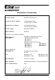
iv Declaration of Conformity Company Name: StorCase Technology, Inc.
v Table of Contents INTRODUCTION ..................................................................................................................... Packaging Information .................................................................................................. Serial Numbers .............................................................................................................. Package Contents ................................................................................................
vi List of Figures Figure 1: Figure 2: Figure 3: Figure 4: Figure 5: Figure 6: Figure 7: Figure 8: Figure 9: Figure 10: Package Contents .......................................................................................... 2 DE300 Receiving Frame and Carrier ............................................................. 3 Receiving Frame Front Panel ......................................................................... 4 Receiving Frame Unit ID Number and Activity Display ..........................
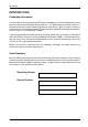
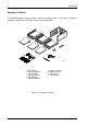
Introduction 1 INTRODUCTION Packaging Information The StorCase Technology Data Express® system is shipped in a container designed to provide protection and prevent damage during shipment. The Data Express unit was carefully inspected before and during the packing procedure at the factory. Bent or broken connectors, or evidence of other damage to the Data Express should be reported to the shipper immediately. Refer to Figure 1 for the package contents.
2 Introduction Package Contents The DE300 package contents should include the following items. If any item is missing or damaged, contact your StorCase dealer for a replacement. 2 1 7 3 4 8 5 Da ta E xpre ss Disk (Not Drive Includ ID Drive Cable Cover (Provi ded) ed) Power I/O Cable Cable Selec t Cable Carrie r Drive Hardw Phillip Moun 3/16 are ting Flats # 6-32(4ea) HD x 0151 Cable Screw # Flat 6-32 s (2Cover HD x 3/16plcs) 6 1. Drive Carrier 2. Receiving Frame 3. #6-32 Phillips Flat Hd.
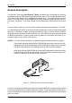
Introduction 3 General Description The StorCase Technology Data Express® DE300 (P/N S20A124) is composed of a receiving frame which supports SCSI Ultra160 interfaces and fits within 5.25" full-height peripheral slots. This 16-bit I/O can support up to 160MByte/sec transfer rates. The receiving frame contains three (3) removable drive carriers designed to provide durable and reliable mounting for 3.5" form factor, low-profile 1" high 80-pin Single-Connect Attachment (SCA) SCSI drives (Figure 2).
4 Introduction Receiving Frame Front Panel (Figure 3) Key Lock/Drive Power Switch: Performs three (3) functions. The key lock assures proper seating of the device carrier within the receiving frame, turns power to the device carrier on and off, and prevents unauthorized removal or installation of the carrier. For the computer to access data on the DE300 disk drive, the key must be turned counterclockwise to the locked position.
Introduction 5 Figure 3: Receiving Frame Front Panel Carrier Removed from Receiving Frame Carrier Installed (unlocked) Carrier Installed (locked) Activity Indicator 0064d Blower Failure The number "2" shown above is for illustration purposes only. It can be any valid unit ID number. The letter "u" and F will appear as illustrated. Figure 4: Receiving Frame Unit ID Number and Activity Display S20A124 User's Guide - Rev. B01 StorCase Technology, Inc.
6 Introduction Receiving Frame Rear Panel (Figure 5) DC Power Connector (J1): The Data Express uses a standard 4-pin DC power connector to accept DC power. I/O Connectors (Drive A, Drive B, Drive C): The input/output connector provides a standard interface for 16-bit wide SCSI signals. Option Pins (J3A, J3B, J3C) Remote Unit ID Selection: Pins 1-8 of these connectors are provided for remote unit SCSI ID selection through the computer system.
Installation 7 INSTALLATION Installing the Drive in the Carrier Preparation While performing the steps in this section, work on a soft surface to prevent excessive shock to the drive being installed. Also refer to the manufacturer's documentation provided with the drive. NOTE: A #2 Phillips screwdriver will be required during this procedure. 1. Remove the drive from its protective packaging. 2. Plastic Drive Bezel: If the drive came equipped with a plastic front bezel, it must be removed. 3.
8 Installation Drive Cover Cover Mounting Screw (2Total) Drive (Not Included) Drive Carrier #6-32 Phillips Flat Hd. Screw (4Total) #6-32 Phillips Pan Hd. Screw Drive Cover Flange Carrier 0433b Cover Disk Drive and I/O Connector (Not Included) (Flush with Rear of Carrier) I/O Connector Carrier Figure 6: Drive Installation Assembly StorCase Technology, Inc. S20A124 User's Guide - Rev.
Installation 9 Installing the Receiving Frame NOTES: For SCSI Ultra160 operation, the DE300 requires Ultra160 chassis and cabling. These newly-designed Ultra160 80-pin SCA DE300 (with blower) carriers are interchangeable with other Ultra160 80-pin SCA DE300 (with blower) receiving frames and older Ultra160 80-pin SCA DE300 receiving frames (without blowers).
10 Installation Table 2: J3A, J3B, J3C Option Pin Signal Descriptions PIN Signal Function 1 2 3 4 5 6 7 8 9 10 11 12 13 14 15 16 17 18 19 20 21 22 ID0 GND ID1 GND ID2 GND ID3 GND BUZZER 5V RLEDA RLEDC FFAULT FFAULT SYNC GND RMTST GND DLYST GND LKA LKB SCSI ID Ground SCSI ID Ground SCSI ID Ground SCSI ID Ground Buzzer Enable 5V Remote LED Anode Remote LED Cathode Fan Failure Indication Fan Failure Indication Drive Synchronization Signal Ground Remote Start Ground Delay Start Ground For Factory Use Only
Installation 11 4. With the drive carriers locked into place inside the receiving frame, install the DE300 receiving frame into the drive opening in the computer or expansion chassis. Use the appropriate guides to position the DE300, and fasten it into place with the four (4) #6-32 Phillips Pan Hd. screws provided. Figure 8 illustrates the location of the mounting holes. Mounting holes are provided on each side and the bottom of the receiving frame to accommodate a variety of mounting configurations.
12 Installation 8. Connect the power cable from the DC power supply in the computer or expansion chassis to the power connector on the DE300 receiving frame. Refer to Figure 5 for the DE300 receiving frame power connector location. 9. Replace any expansion boards that may have been removed earlier. Replace the system cover according to the manufacturers instructions. 10. Reconnect any system or peripheral cables removed earlier. 11. Turn ON power to the computer.
Installation 13 WARNING: Selecting an invalid ID number, or selecting the same unit ID number on different devices may cause unpredictable results and the computer system may not recognize the installed device(s). If the computer system can not recognize the boot disk, the computer may fail to start-up properly. 4. After selecting an appropriate unit ID number, replace the DE300 carrier in the receiving frame, and LOCK IT INTO PLACE. 5.
14 Installation Adjusting the Spin Down/Up Timer NOTE: The timer for device spin down is controlled by a small selector, located in a cutout on the side of the DE300 receiving frame as shown in Figure 10. The amount of time required for a drive to spin down is approximately 15 seconds or more. This number can vary depending on the type of SCSI device and manufacturer (some drives may require 45 seconds or more). The factory configuration is set for 20 seconds.
Appendix A - Specifications/Dimensions 15 APPENDICES S20A124 User's Guide - Rev. B01 StorCase Technology, Inc.
16 Appendix A - Specifications/Dimensions Appendix A - Specifications/Dimensions SCSI Data Express subsystems conform to the Small Computer Systems Interface (SCSI) Standard set by the American National Standards Institute (ANSI).
Appendix A - Specifications/Dimensions Receiving Frame with Carriers Installed 17 3.12 (79.2mm) 2.06 (52.3mm) 0.47 (11.9mm) 3.38 (85.9mm) 1.25 (31.8mm) 0.47 (11.9mm) 0.39 (9.9mm) 5.88 (149.4mm) #6-32 x 8 (Side) 6.67 (169.4mm) 0.03 (0.8mm) 5.50 (139.7mm) #6-32 x 4 (Bottom) 3.12 (79.2mm) Carrier Only 1.07 (27.2mm) 4.67 (118.6mm) 6.36 (161.5mm) 3.75 (95.3mm) 4.67 (118.6mm) 1.75 (44.
18 Appendix B - Attaching the ON/OFF Key Appendix B - Attaching the ON/OFF Key The following information will provide the necessary steps to attach the ON/OFF key to the key lock mechanism so that it is non-removable, preventing accidental key loss. The procedure can be reversed at a later date to revert back to a removable key. 1. Make certain power is OFF to the receiving frame. Locate the rectangular shaped key lock mechanism access hole on the inside of the receiving frame.
Appendix C - Optional Accessories 19 Appendix C - Optional Accessories Carrying Case Drive Carrier 0460d S20E104 Carrying Case Figure C-1: Carrying Case The optional molded plastic carrying case is designed to transport the DE300 carrier from one site to another in a safe, impact and moisture resistant environment. Its compact dimensions, 7 long x 9 wide x 4 high, make it easy to carry and to store. The foam lining is contoured to fit a single Data Express carrier with a 1" form factor.
20 Appendix C - Optional Accessories This Page Left Blank Intentionally. StorCase Technology, Inc. S20A124 User's Guide - Rev.
Reader's Comments 21 Reader's Comments Please take a few moments when your computer system is up and running to send us your ideas and suggestions for improving our products and documentation.
Reader's Comments CUT ALONG THIS LINE FROM BOTTOM TO TOP OF PAGE 22 FOLD ALONG THIS LINE AND STAPLE SHUT NO POSTAGE NECESSARY IF MAILED IN THE UNITED STATES B U S I N E S S R E P LY M A I L FIRST CLASS MAIL PERMIT NO. 10686 SANTA ANA, CA POSTAGE WILL BE PAID BY ADDRESSEE TECHNOLOGY CORPORATION 17600 NEWHOPE STREET FOUNTAIN VALLEY CA 92708-9885 StorCase Technology, Inc. S20A124 User's Guide - Rev.