
Instruction Manual

StorCase Technology, Inc. S20A120 User's Guide - Rev. A01
10 Installation
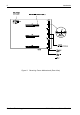
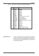
PIN Signal Function
1 ID0 SCSI ID
2 GND Ground
3 ID1 SCSI ID
4 GND Ground
5 ID2 SCSI ID
6 GND Ground
7 ID3 SCSI ID
8 GND Ground
9 GND Drive Synchronization Signal
10 GND Spare Ground
11 RLEDC Remote LED Cathode
12 RLEDA Remote LED Anode
13 DFAULT Force Drive Fault Signal to Display
14 GND Ground
15 CIF1 Reserved
16 GND Ground
17 CIF2 Reserved
18 GND Ground
19 CIF3 Reserved
20 GND Ground
21 LKA Disable Isolator Functions
22 LKB Disable Isolator Functions
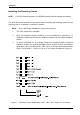
IMPORTANT NOTE: In order to use remote ID selection from a computer or expansion
chassis, the Unit ID number on the Data Express receiving frame
must be set to "0" with the provided alignment tool. Refer to the
section "Selecting the Unit ID Number" later in this manual for the
Unit ID selection procedure.
Table 1: J3A1, J3B1, J3C1 Option Pin Signal Descriptions