
User Manual

StorCase Technology, Inc. S20A114 User's Guide - Rev. A01
10 Installation
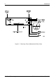
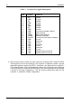
PIN Signal Function
1 ID0 SCSI ID
2 GND Ground
3 ID1 SCSI ID
4 GND Ground
5 ID2 SCSI ID
6 GND Ground
7 ID3 SCSI ID
8 GND Ground
9 GND Drive Synchronization Signal
10 GND Spare Ground
11 RLEDC Remote LED Cathode
12 RLEDA Remote LED Anode
13 DFAULT Force Drive Fault Signal to Display
14 GND Ground
15 CIF1 Reserved
16 GND Ground
17 CIF2 Reserved
18 GND Ground
19 CIF3 Reserved
20 GND Ground
21 LKA Disable Isolator Functions
22 LKB Disable Isolator Functions
Table 1: J3 Option Pin Signal Descriptions
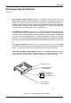
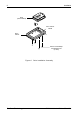
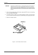
4. With the drive carrier locked into place inside the receiving frame, install the DE75
receiving frame into the drive opening in the computer or expansion chassis. Use the
appropriate guides to position the DE75 , and fasten it into place with four (4) #6-32 x
1/4 screws provided. Figure 8 illustrates the location of the mounting holes. Mounting
holes are provided on each side and the bottom of the receiving frame to accommodate
a variety of mounting configurations. Use the mounting holes which best suit the
computer or expansion chassis configuration.